Lenze · 8400 HighLine · Reference manual · DMS 12.0 EN · 06/2017 · TD23 539
8 Basic drive functions (MCK)
8.4 Basic settings
_ _ _ _ _ _ _ _ _ _ _ _ _ _ _ _ _ _ _ _ _ _ _ _ _ _ _ _ _ _ _ _ _ _ _ _ _ _ _ _ _ _ _ _ _ _ _ _ _ _ _ _ _ _ _ _ _ _ _ _ _ _ _ _
8.4.3.2 Hardware limit switches
The travel range limits are monitored by means of limit switches via the inputs bLimitSwitchPos and
bLimitSwitchNeg of the LS_MotionControlKernel
system block.
• The two inputs react to the TRUE state.
•In TA "Table positioning"
, the two inputs are connected to the digital inputs provided for
connection of the limit switches.
Behaviour when hardware limit switches are active
If one of the two monitoring inputs is set to TRUE:
• The error response "TroubleQuickStop" takes place in the Lenze setting, i.e. the drive is brought
to a standstill in the deceleration time set for the quick stop function and does so irrespective of
the setpoint selection. The error response can be parameterised in C00595/1
and C00595/2.
• The error message "Ck01: Pos. HW limit switch" or. "Ck02: Neg. HW limit switch" is entered in
the logbook of the inverter.
• Bit 10 ("Pos. HW-Limit Detected") or bit 11 ("Neg. HW-Limit Detected") is set in the MCK status
word.
• Depending on the parameterised fault response, the drive cannot traverse until the error has
been acknowledged.
Stop!
The limit switches are only evaluated if the limit switches for the respective operating
mode have been activated (see the following table)!
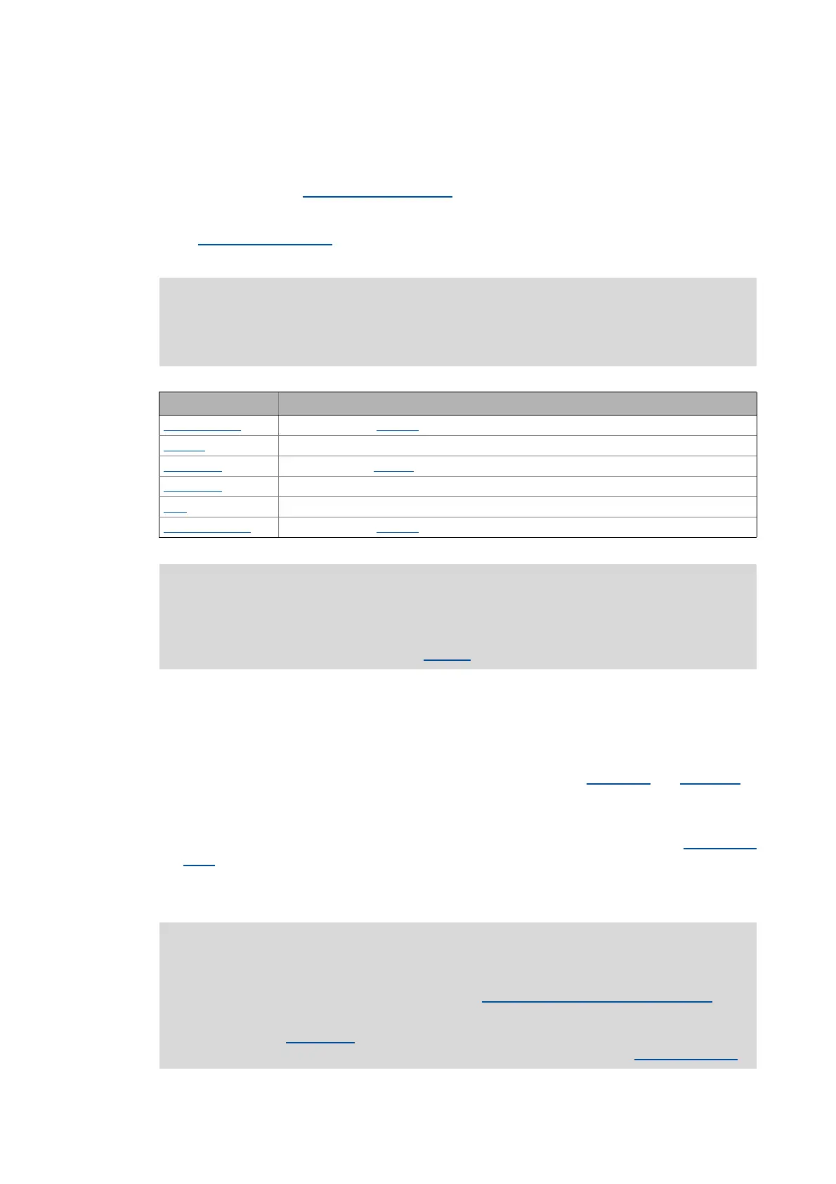
Operating mode Hardware limit switch effective
Speed follower
Yes (adjustable in C01219 - bit 2)
Homing Depending on the selected homing mode (see description of the homing modes)
Manual jog
No (adjustable in C01230 - bit 2)
Positioning
Yes
Stop
Yes
Position follower
Yes (adjustable in C01218 - bit 2)
Note!
If the digital inputs used for the connection of the limit switches are to be designed in a
fail-safe manner (activation at LOW level), you simply change the terminal polarity of
the corresponding digital inputs in C00114
.
Note!
An activated limit switch can be retracted again by manual jog in the opposed direction
or with the "Retract limit switch" function.Retracting of an operated limit switch
( 581)
Only in the "Manual jog
" operating mode, retracting of the limit switch resets bit 10
("Pos. HW-Limit Detected") or bit 11 ("Neg. HW-Limit Detected") in the MCK status word
.

 Loading...


