7 Technology applications
7.3 TA "actuating drive speed (AC Drive Profile)"
406
Lenze · 8400 HighLine · Reference manual · DMS 12.0 EN · 06/2017 · TD23
_ _ _ _ _ _ _ _ _ _ _ _ _ _ _ _ _ _ _ _ _ _ _ _ _ _ _ _ _ _ _ _ _ _ _ _ _ _ _ _ _ _ _ _ _ _ _ _ _ _ _ _ _ _ _ _ _ _ _ _ _ _ _ _
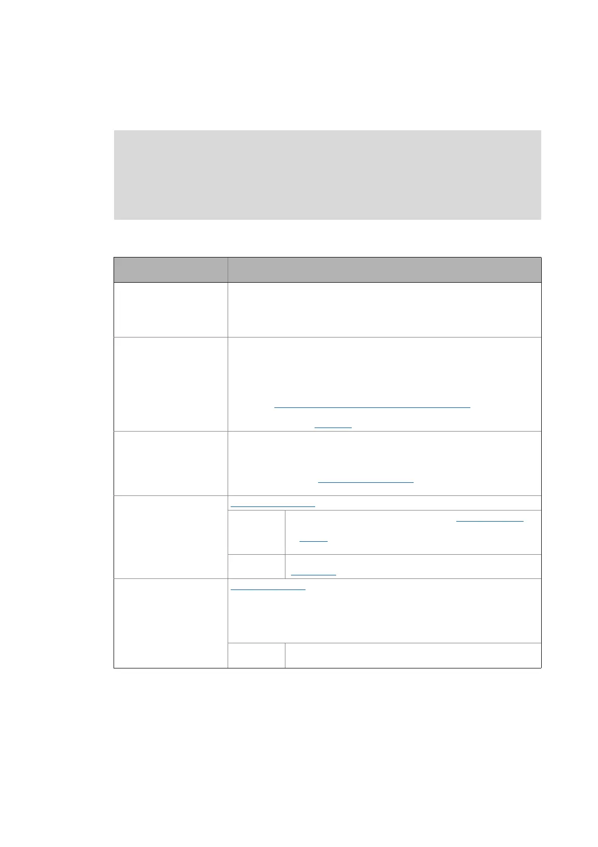
7.3.3 Internal interfaces | application block "LA_NCtrl"
Inputs
Note!
The connectors greyed out in the following table are hidden in the function block editor
in the Lenze setting.
• These connections can be shown via the Connector visibilities command in the
Context menu of the application block.
Designator
Data type
Information/possible settings
wCANDriveControl
WORD
Input for CAN control word
• Is not used in this configuration and is thus set to the permanent value "9" in the
Lenze setting (SwitchOn = TRUE and EnableOperation = TRUE).
• For the evaluation of the AC Drive Profile control word received via fieldbus, the
wMCIDriveControl input is used in the control modes 30: CAN" and "40: MCI".
wMCIDriveControl
WORD
Input for the AC Drive Profile control word received via fieldbus
• The AC Drive Profile control word operates the inverter in compliance with the
assembly output object instances 20 ... 23. For this purpose, the control bits are
evaluated and lead to a corresponding modification of the control signals
bFailReset, bRFG_0 and bSetSpeedCcw which results in the AC Drive-specific
behaviour.
• See the "Process data assignment for fieldbus communication
" subchapter for a
detailed description of the individual control bits.
• Display parameter: C01351/1
wSMControl
WORD
Interface to the optional safety system.
• Setting control bit 0 ("SafeStop1") in this control word causes e.g. the automatic
deceleration of the drive to standstill within this application (in the Motion
Control Kernel).
• See the subchapter "Interface to safety system
" of the chapter on basic drive
functions for a detailed description of the individual control bits.
bCInh
BOOL
Enable/inhibit inverter
FALSE Enable inverter: The inverter switches to the "OperationEnabled"
device status if no other source for controller inhibit is active.
• C00158
provides a bit coded representation of all active
sources/triggers of a controller inhibit.
TRUE Inhibit inverter (controller inhibit): The inverter switches to the
"SwitchedOn
" device status.
bFailReset
BOOL
Reset error message
• In the Lenze setting this input is connected to the digital input controller enable
so that a possibly existing error message is reset together with the controller
enable (if the cause for the fault is eliminated).
• In case of control via fieldbus (NetCtrl=1): This input is OR'd with bit 2 ("fault
reset") of the AC Drive Profile control word.
TRUE The current fault is reset, if the cause for the fault is eliminated.
• If the fault still exists, the error status remains unchanged.

 Loading...


