Lenze · 8400 HighLine · Reference manual · DMS 12.0 EN · 06/2017 · TD23 241
5 Motor control (MCTRL)
5.9 Servo control (SC)
_ _ _ _ _ _ _ _ _ _ _ _ _ _ _ _ _ _ _ _ _ _ _ _ _ _ _ _ _ _ _ _ _ _ _ _ _ _ _ _ _ _ _ _ _ _ _ _ _ _ _ _ _ _ _ _ _ _ _ _ _ _ _ _
Special cases may require further optimisation steps:
Tip!
In order to traverse a typical speed profile for optimisation of motor control, you can also
use the basic function "Manual jog
" with appropriately adapted manual jog parameters if
this basic function is supported by the selected technology application.
( 573)
5.9.4.1 Optimise current controller
An optimisation of the current controller is sensible since the two control parameters gain (C00075)
and reset time (C00076
) depend on the required maximum current and the set switching
frequency.
• Gain and reset time can be calculated as per the following formulae:
Optimisation steps
1 Setting the current setpoint filter (band-stop filter)
. ( 248)
• In order to suppress or damp (mechanical) resonant frequencies, a current setpoint filter is integrated in
the speed control loop which is switched off in the default setting but can be parameterised accordingly,
if required.
Then readjust the speed controller: Optimise speed controller
. ( 242)
2. Adapting the max. acceleration change (jerk limitation)
. ( 249)
3. Optimising the behaviour of the asynchronous motor in the field weakening range
. ( 252)
Note!
An optimisation of the current controller should generally be carried out unless a power-
adapted standard asynchronous motor is used or the motor has been selected from the
motor catalogue of the »Engineer«!
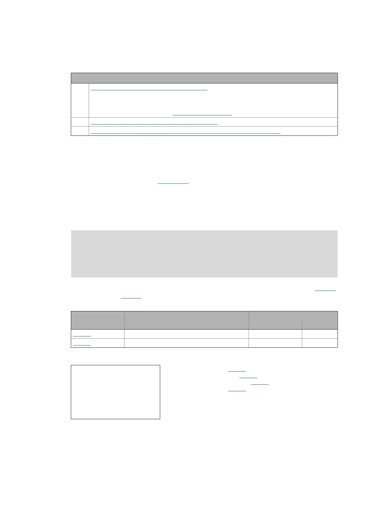
Parameters Info Lenze setting
Value Unit
C00075 Vp current controller 7.00 V/A
C00076 Ti current controller 10.61 ms
V
p
= Current controller gain (C00075)
T
i
= Current controller reset time (C00076)
L
ss
= Motor stator leakage inductance (C00085)
R
s
= Motor stator resistance (C00084)
T
E
= Equivalent time constant (= 500 μs)
V
p
L
ss
H[]
T
E
s[]
----------------
=
T
i
L
ss
H[]
R
s
Ω[]
----------------
=

 Loading...


