Lenze · 8400 HighLine · Reference manual · DMS 12.0 EN · 06/2017 · TD23 787
13 Synchronisation of the internal time base
_ _ _ _ _ _ _ _ _ _ _ _ _ _ _ _ _ _ _ _ _ _ _ _ _ _ _ _ _ _ _ _ _ _ _ _ _ _ _ _ _ _ _ _ _ _ _ _ _ _ _ _ _ _ _ _ _ _ _ _ _ _ _ _
13 Synchronisation of the internal time base
In a drive system, synchronising the internal time bases of all inverters involved makes sense
because cyclic process data should be processed synchronously in all drives.
• One of the following signal sources can be used for automatic synchronisation of the internal
time base of the inverter:
• CAN bus ("CAN on board") sync telegram
•MCI sync signal of a plugged-in communication module
(EtherCAT, PROFINET or Powerlink)
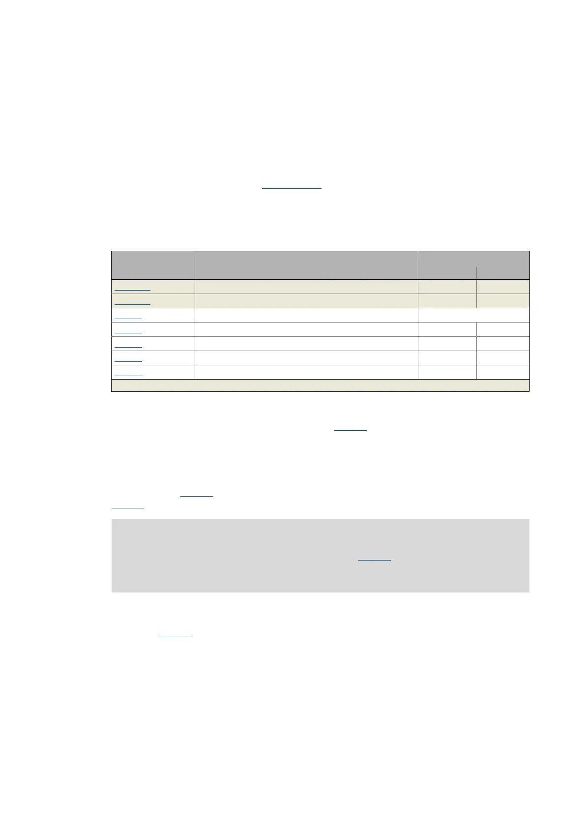
Short overview of the parameters for the synchronisation of the internal time base:
Sync signal source
The synchronisation signal source can be selected in C01120
. As a general rule, only one source can
be used to synchronise the internal time base.
Sync cycle time setpoint
Time with which the internal phase-locking loop (PLL) expects the synchronisation signals. The time
must be set in C01121
in accordance with the cycle of the synchronisation source selected in
C01120
.
Example: For the CAN bus, 2 ms has been selected as interval between two synchronisation signals.
If the CAN bus is to be used as synchronisation source, a cycle time setpoint of 2000 μs must be
selected in C01121
.
Parameters Info Lenze setting
Value Unit
C00370/1 CAN Sync instant of transmission - μs
C00370/2 Sync instant of reception - μs
C01120
Sync signal source Off
C01121
Sync cycle time setpoint 1000 μs
C01122
Sync phase position 0 μs
C01123
Sync window 100 μs
C01124
Sync correction width 300 ns
Greyed out = display parameter
Note!
• Only integer multiples of 1000 μs can be set in C01121.
• Intelligent communication modules usually define the cycle time setpoint derived
from the bus cycle. In this case, a manual change is not possible.

 Loading...


