5 Motor control (MCTRL)
5.11 Encoder/feedback system
280
Lenze · 8400 HighLine · Reference manual · DMS 12.0 EN · 06/2017 · TD23
_ _ _ _ _ _ _ _ _ _ _ _ _ _ _ _ _ _ _ _ _ _ _ _ _ _ _ _ _ _ _ _ _ _ _ _ _ _ _ _ _ _ _ _ _ _ _ _ _ _ _ _ _ _ _ _ _ _ _ _ _ _ _ _
5.11.1 Parameterising digital inputs as encoder inputs
The function of the digital inputs DI1/DI2 and DI6/DI7 is defined via C00115/1...2.
To be able to use the digital inputs as encoder inputs, select 2, 3, or 4 (Lenze recommendation: 2) in
C00115/1
or C00115/2, depending on the input terminals used.
Related topics:
Digital input terminals
( 323)
Using DI1(6) and DI2(7) as frequency inputs
( 327)
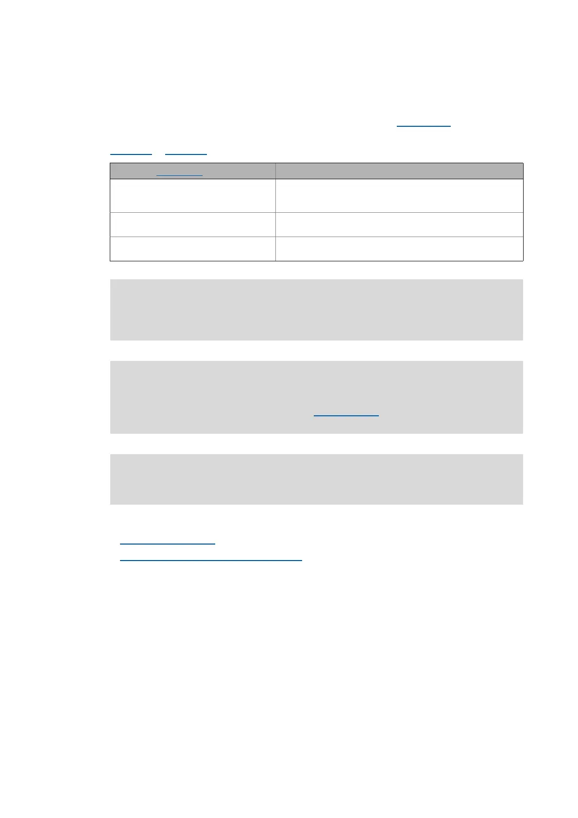
Selection in C00115/1...2 Function
2: DI1(6)&DI2(7)=FreqIn (2-track) DI1/6 and DI2/7 = 2-track frequency input
• Permits a two-track evaluation of the encoder including correct
detection of the direction of rotation.
3: DI1(6)=FreqIn / DI2(7)=Direction DI1/6 = 1-track frequency input
DI2/7 = specification of direction
4: DI1(6)=CountIn / DI2(7)=In DI1/6 = counter input
DI2/7 = digital input
Danger!
For single-track evaluation, make sure that the sign is correctly specified. Otherwise, the
motor may overspeed.
Note!
If the digital inputs are parameterised as encoder inputs, the corresponding output
signals (bIn1/bIn2 and bIn6/bIn7) at the LS_DigitalInput
system block are automatically
set to FALSE.
The wiring diagram and assignment of the input terminals are described in the 8400
hardware manual . The hardware manual has been stored in electronic form on the data
carrier supplied with the 8400 inverter.

 Loading...


