9 Diagnostics & error management
9.6 Monitoring
640
Lenze · 8400 HighLine · Reference manual · DMS 12.0 EN · 06/2017 · TD23
_ _ _ _ _ _ _ _ _ _ _ _ _ _ _ _ _ _ _ _ _ _ _ _ _ _ _ _ _ _ _ _ _ _ _ _ _ _ _ _ _ _ _ _ _ _ _ _ _ _ _ _ _ _ _ _ _ _ _ _ _ _ _ _
9.6 Monitoring
The inverter is provided with various monitoring functions which protect the drive against
impermissible operating conditions.
• If a monitoring function responds,
• an entry will be made into the Logbook
of the inverter,
• the response (TroubleQSP, Warning, Fault, etc.) set for this monitoring function will be
triggered,
• the status of the internal device control changes according to the selected response,
controller inhibit is set, and the "DRV- ERR" LED on the front of the inverter goes on:
Related topics:
LED status displays of the device status
( 625)
Device state machine and device states
( 112)
Device overload monitoring (Ixt)
( 298)
Motor load monitoring (I2xt)
( 299)
Motor temperature monitoring (PTC)
( 302)
Brake resistor monitoring (I2xt)
( 303)
Motor phase failure monitoring
( 305)
Mains phase failure monitoring
( 308)
Maximum current monitoring
( 308)
Maximum torque monitoring
( 310)
Encoder open-circuit monitoring
( 311)
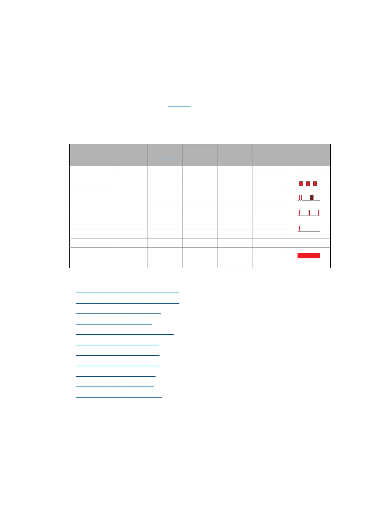
Response Entry in the
logbook
Display in
C00168
Pulse inhibit Disable drive
function
Acknowledge
ment
required
LED "DRV-ERR"
None OFF
Fault
Trouble
TroubleQSP
WarningLocked
Warning
Information OFF
System fault Mains
switching
is required!

 Loading...


