February, 2008
4-225
WorkCentre 5225, 5230
ADJ 9.2.1
Repairs and Adjustments
Launch Version
ADJ 9.2.1 Edge Erase Value Adjustment
Purpose
To correct the Lead, Tail Edge and both Side Edge (rear/front) erase values.
NOTE: The IOT Lead Edge/Side Edge Registration must be adjusted.
Check
1. Access Diagnostic Routines.
a. Enter UI Diagnostics (UI Diagnostic Mode).
2. Select NVM Read/Write.
3. Set Chain-Link Number 749-516 (Image Area) to 0.
4. Specify a tray with paper. Make a black copy with the Platen Cover open.
5. Check that the white sections of the Lead, Tail and Side Edges are 2mm.
Adjustment
1. Access Diagnostic Routines.
a. Enter UI Diagnostics (UI Diagnostic Mode).
2. Select NVM Read/Write.
3. Adjust the measured values using the following NVM so that the measured values fall
within the specifications (2mm).
If the setting value is increased, the erase value increases.
4. After adjustment, make another black copy without using any originals and leaving the
Platen Cover open.
5. Repeat the procedure until the white sections of the Lead, Tail and Side Edges fall within
the specifications (2mm).
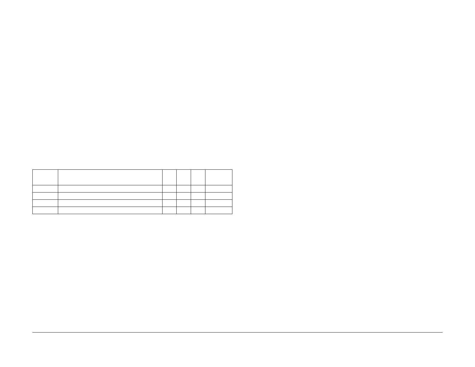
Table 1 NVM List
Chain
Link
Name Min.
Initia
l
Max Increment
749-522 END ERASE OFFSET VALUE ADJUSTMENT 0 50 99 0.363mm
749-523 SIDE NORMAL ERASE ADJUSTMENT 0 8 16 0.254mm
749-524 TOP NORMAL ERASE ADJUSTMENT 0 9 18 0.217mm
749-527 END NORMAL ERASE ADJUSTMENT 0 9 18 0.217mm
 Loading...