2008T Troubleshooting Guide
P/N 490292 Rev. A
F- 10.0.0 BAD ACFS SIGNAL
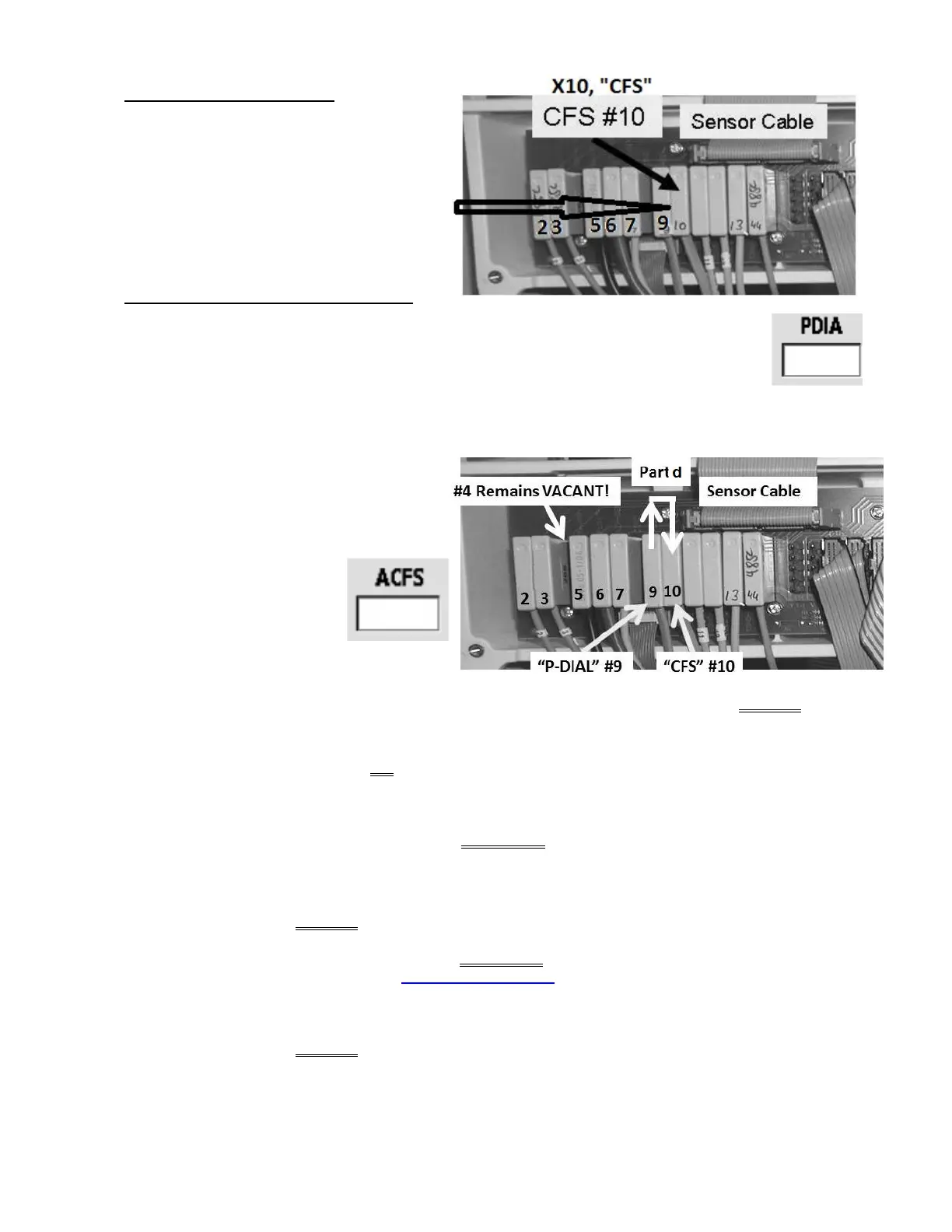
a) Figure right, ENSURE the CFS #10
Pressure Transducer’s connector is
plugged PROPERLY into the
distribution board.
b) See procedure number F- 10.1.0
(page 111).
F- 10.1.0 CFS PLUGGED IN PROPERLY
a) Call debug screen 10. If all procedures were performed correctly PDIA (middle column)
= between 3.5 and 6.5.
b) Unplug the CFS’s connector from position X10, “CFS”.
c) Using a flashlight, check inside the vacant “X10” position. If corrosion or damaged pins are located
this may be the problem!
d) Figure right, plug the Dialysate
Pressure Sensor’s (#9) connector
into the CFS Pressure Sensor’s. “P-
DIAL” → “CFS”.
e) Does
ACFS (lower
right) go to between 4.0
and 6.0?
Yes ACFS between 4.0 and 6.0! The CFS Pressure Sensor #10* is bad. *To LOCATE the
CFS Pressure Sensor #10 refer to Figure 21 (page 100).
No ACFS is less than 4.0 OR more than 6.0! Leaving PDIA in CFS for now, FIVE (5) possible bad
components: 1) Bad Actuator-Test Board
a
OR; 2) Bad Sensor Board
b
OR; 3) Bad Sensor
Board cable OR; 4) Bad distribution board OR;5) Bad motherboard.
a
A) With the power off, swap in a known good Actuator-Test
1
Board; B) IMPORTANT!
Return Dialysis Program (“Select Program” → ‘Dialysis’ → ‘Enter’); C) If ACFS is between
4.0 and 6.0 the previous Actuator-Test Board is bad.
1
To LOCATE the board refer to Figure 4A (page 10).
b
A)
With the power off, swap in a known good Sensor Board
2
; B) Place the machine into
T and C Mode (refer to OPERATING MODES (page 19); C) IMPORTANT! Return to
Dialysis Program)!; D) If ACFS now = between 4.0 and 6.0 the previous Sensor Board is
bad.
2
To LOCATE the Sensor board see Figure 4A (page 10).

 Loading...


