2008T Troubleshooting Guide
P/N 490292 Rev. A
1) IF (and ONLY if) ONLY Valves #30 AND #26 ‘dots’ are blue AND all others are white:
See procedure number VE- 2.0.1 (page 216).
2) ALL other scenarios: Proceed to
page 223, procedure number VE- 7.0.0.
VE- 2.0.1 ONLY VALVES #30 AND #26 ‘DOTS’ ARE BLUE
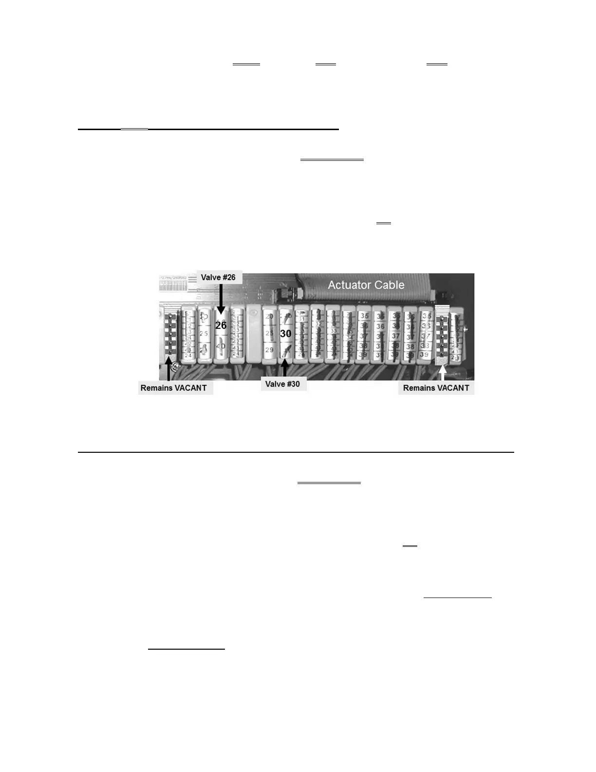
a) At the distribution board (Figure below), unplug Valve #26’s connector.
b) Watch the Balancing Chamber Valve ‘dots’ for thirty (30) seconds. Do they begin to cycle between white
and blue?
Yes The Balancing Chamber Valves to cycle! Valve #26 OR its blue wire harness is bad.
No The Balancing Chamber Valve ‘dots’ REMAIN white! See procedure number VE- 2.0.2
(page 216).
Figure 38 – Valves #26 AND #30
VE- 2.0.2 VALVE #26 UNPLUGGED AND THE BALANCING CHAMBER VALVES REMAIN WHITE
a) At the distribution board, Figure above, unplug Valve #30’s connector.
b) Watch the Balancing Chamber Valve ‘dots’ for up to thirty (30) seconds. Do they begin to cycle between
white and blue?
Yes The Balancing Chamber Valves begin to cycle! Valve #30 OR its blue wire harness is bad.
No A) CAREFULLLY return ALL Valve connectors to the distribution board.
B) Turning the machine off first, swap in each component (see Component List below),
one at a time, returning to Dialysis Program in between, until VERR remains = 0 for ten
(10) minutes indicating the last component swapped in is the
Component List:
1) Actuator-Test Board; 2) Actuator Cable; 3) Distribution board

 Loading...


