2008T Troubleshooting Guide
P/N 490292 Rev. A
TMP- 3.1.0 ACFS BETWEEN 3.5 AND 6.0 / ISOLATE DIALYSATE PRESSURE TRANSDUCER
This procedure uses the CFS transducer (known good) to check the dialysate pressure transducer circuit.
a) Leave the diayzer lines out of the shunt!
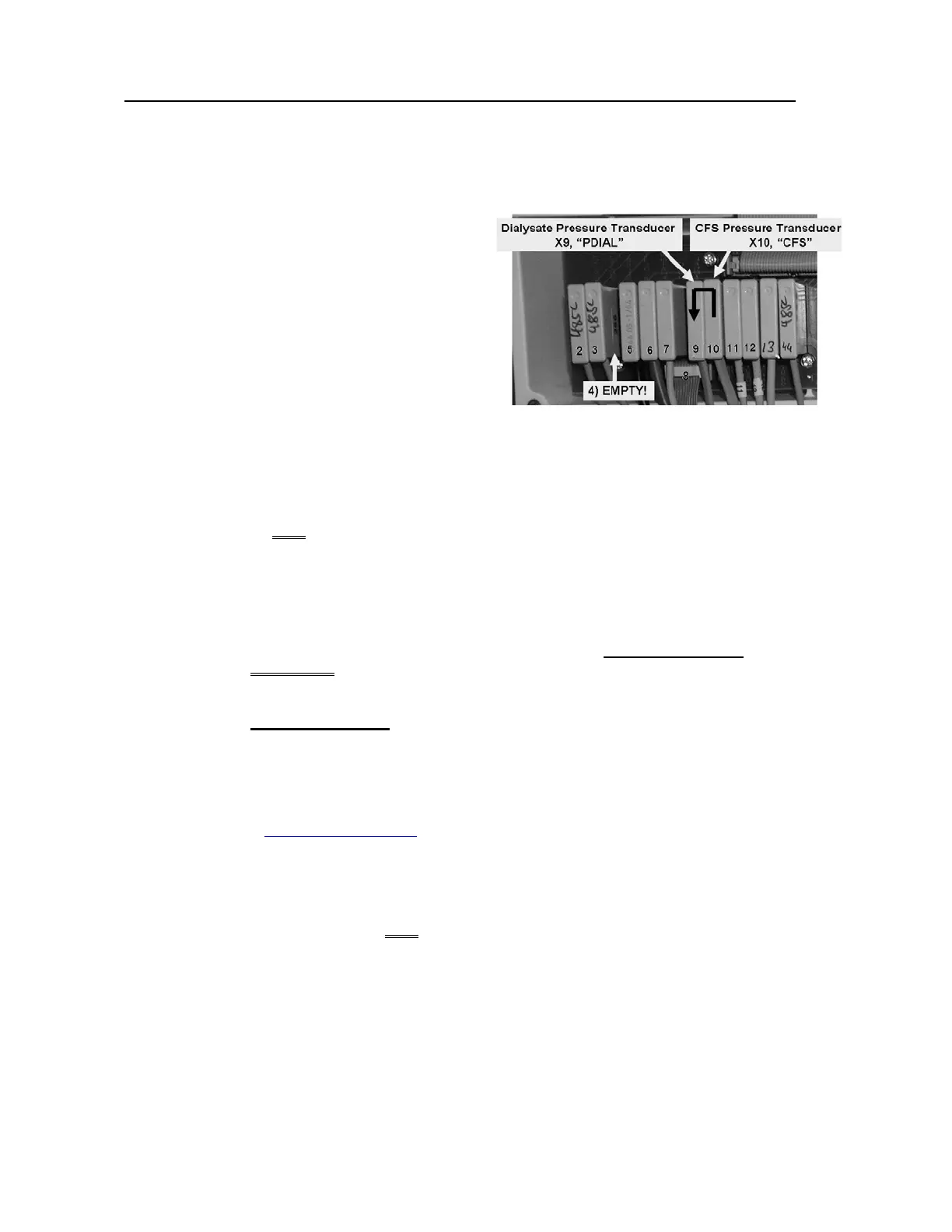
b) Figure right, unplug the Dialysate Pressure
Transducer #9 from distribution board position
“x9, PDIAL”.
c) Using a flashlight, check inside the vacant x9
position for corrosion and/or damaged male
pins.
d) Figure right, plug the CFS Transducer’s
connector (#10) into the Dialysate Pressure
Transducer’s position “x9, “PDIAL”.
e) From debug screen 10, is PDIA (middle column) between 3.5 and 6.0?
Yes PDIA between 3.5 and 6.0! Dialysate Pressure Transducer #9 is bad.
No PDIA is NOT between 3.5 and 6.0! Perform parts A THROUGH E below:
A) Leave CFS (#10) plugged into “X9, PDIAL” for parts B through E.
B) Turn the machine OFF!
C) One at a time, swap in the listed components, (see COMPONENT LIST below), with
known good and in between, until PDIA is between 3.5 and 6.0 indicating the last
component swapped in is bad!
COMPONENT LIST: 1) Sensor Board
1, 2
;
2) Actuator-Test Board
1
; 3) Sensor Board cable;
4) Functional Board
1, 2
; 5) Distribution board
1
; 6) Motherboard.
1
To LOCATE the boards, refer to Figure 4A (page 10)
2
To prevent “Cond Offset Failure”, place the machine into T and C Mode (refer to
OPERATING MODES (page 19)
D) Return to Dialysis Program but leave [Dialysate Flow] off!
E) If screen 10’s PDIA is now between 3.5 and 6.0 the last component swapped in was the
problem. If PDIA is NOT between 3.5 and 6.0 return to part B.

 Loading...


