2008T Troubleshooting Guide
P/N 490292 Rev. A
SECTION 14 - UF (ULTRAFILTRATION) PUMP PROBLEMS
UF- 1.0.0 ISOLATE UF CIRCUIT
THREE checks! Answer for all three at Check #3:
Check #1: Does the “UF Pump Alarm” banner appear?
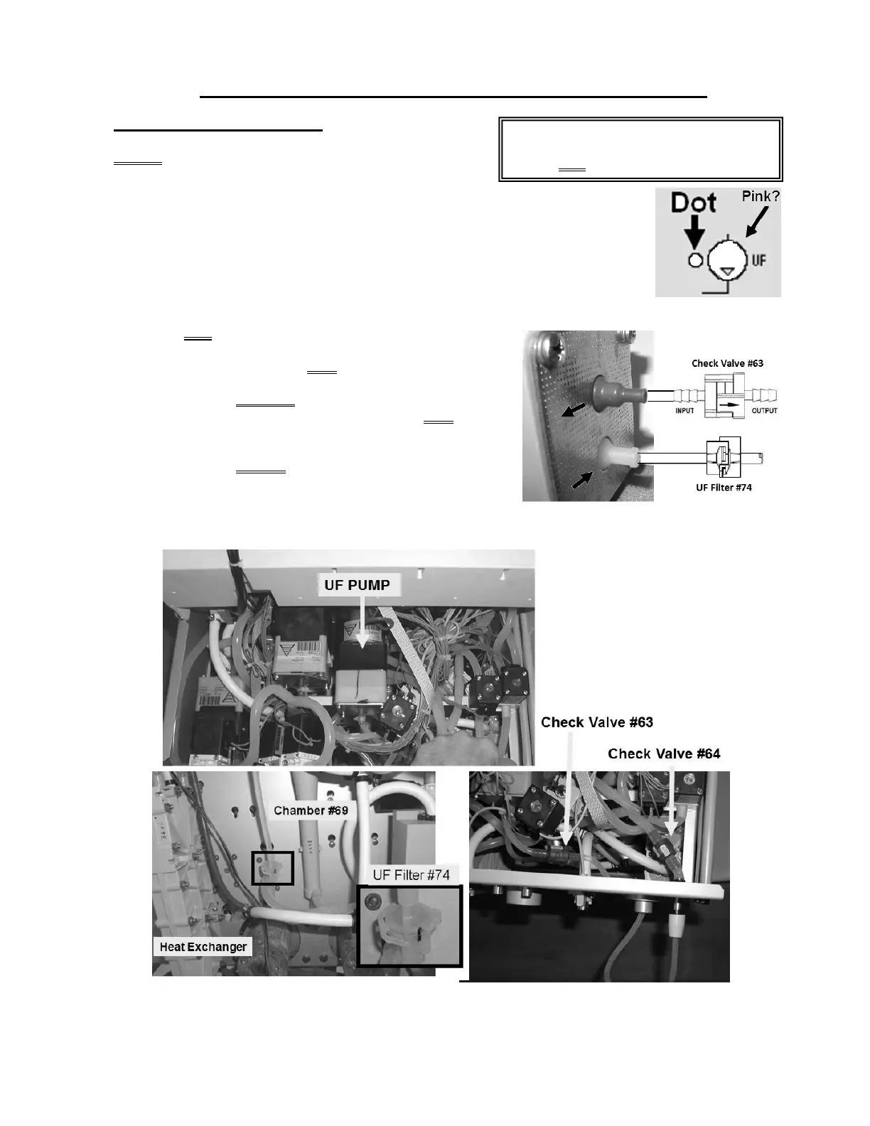
Check #2: Call debug screen 0. Figure right, is the UF Pump ‘dot’ ALWAYS blue?
(i.e. NEVER white)
Check #3: Figure right, is the UF Pump symbol PINK?
Yes (to any of the three): Proceed to
page 553, procedure number UF- 5.0.0.
No (to ALL three): Perform parts a AND b below:
a) Per the Figures below AND right, TWO more checks:
Check #4: ENSURE the UF Pump is installed with
its output, red or blue, nozzle at the TOP AND is
mated to the mounting plate’s output (→) arrow.
Check #5: ENSURE the OUTPUT tubing is
connected to UF Check Valve #63; INPUT tubing, at
the white nozzle, to UF Filter #74.
b) If no problems were located above see procedure number UF- 1.4.0 (page 549).
Figure 85 – Hydraulics Top / Front Views
The UF Pump ‘dot’ toggles between white
and blue when the UF Pump strokes. It
should NOT be constantly blue!

 Loading...


