2008T Troubleshooting Guide
P/N 490292 Rev. A
T- 1.0.3 ISOLATE HEATER
A) To avoid shock “Select Program” REMAINS up till instructed!
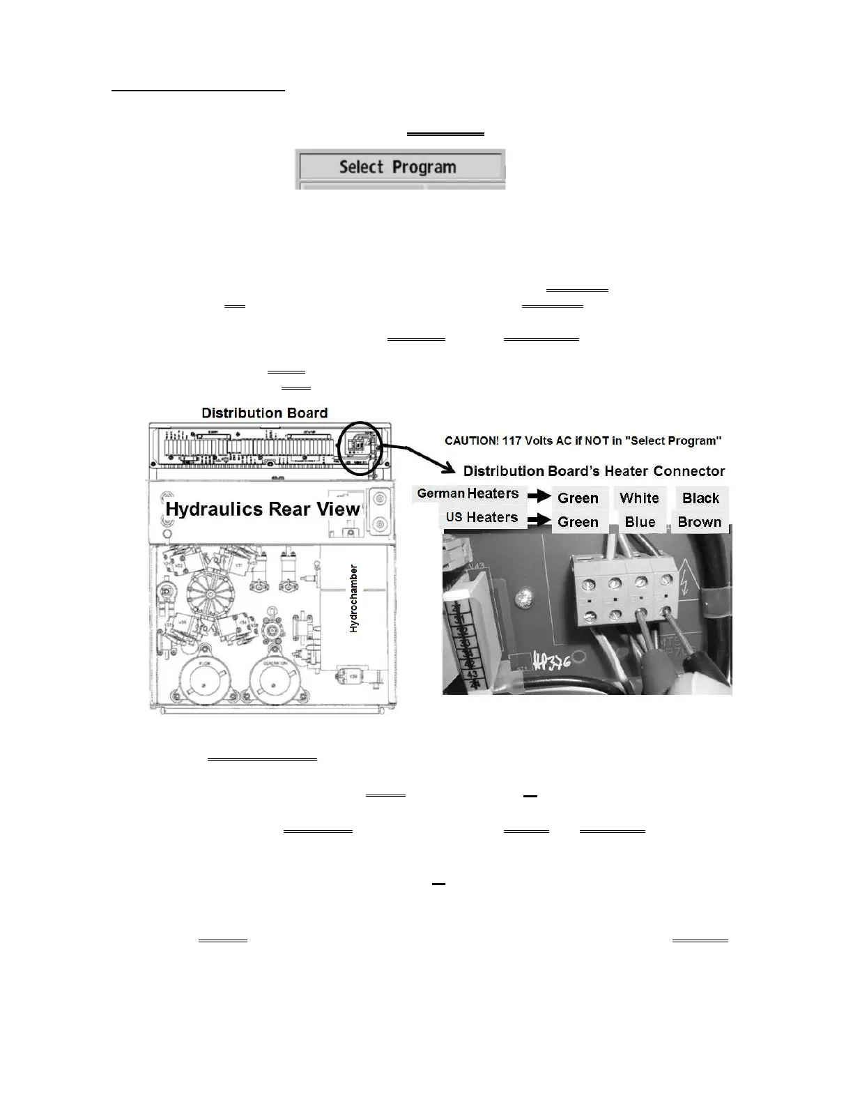
B) Figure below, remove the distribution board cover.
C) At the green eight-pin Heater Connector, THREE (3) checks:
CHECK #1: From RIGHT-TO-LEFT, the BOTTOM four (4) wires MUST BE brown, blue, green/yellow
OR black, white, green; the TOP three (3) wires MUST BE brown, blue, green/yellow!
CHECK #2: Yank on all of the wires to ENSURE they are SECURELY attached.
CHECK #3: If (and ONLY if) signs of burning is seen indicate the wires may not have been securely
attached AND the distribution board needs to be replaced!
D)
Set your CALIBRATED volt meter to resistance (Ω)!
E) Touch the leads together. The meter MUST read less than 0.3 Ω!
F) Figure above, measure BETWEEN the Heater Connector’s BLUE and BROWN wires. TWO (2)
possible scenarios:
1) IF (and ONLY if) between 8.0 and 13.0
Ω: The heater is good! See procedure number T-
1.0.4 (page 236).
2) ALL OTHER scenarios (possibly about 20 Ω or “OL”): The heater* is bad! *To LOCATE the
heater refer to Figure 28 (page 140).

 Loading...


