2008T Troubleshooting Guide
P/N 490292 Rev. A
F- 5.1.0 BALANCING CHAMBER VALVES WIRED CORRECTLY
a) Call debug screen 6.
b) Watch BC Switch (middle column) for thirty (30) FULL seconds. Does it REMAIN
ALWAYS = 897?
Yes BC Switch ALWAYS = 897! See procedure number F- 5.1.1 (page 56).
No BC Switch IS NOT always = 897! Proceed to
page 57, procedure number F- 5.2.0 (page 57).
F- 5.1.1 BC SWITCH ALWAYS = 897 / ISOLATE PRESSURE SENSOR CONNECTIONS
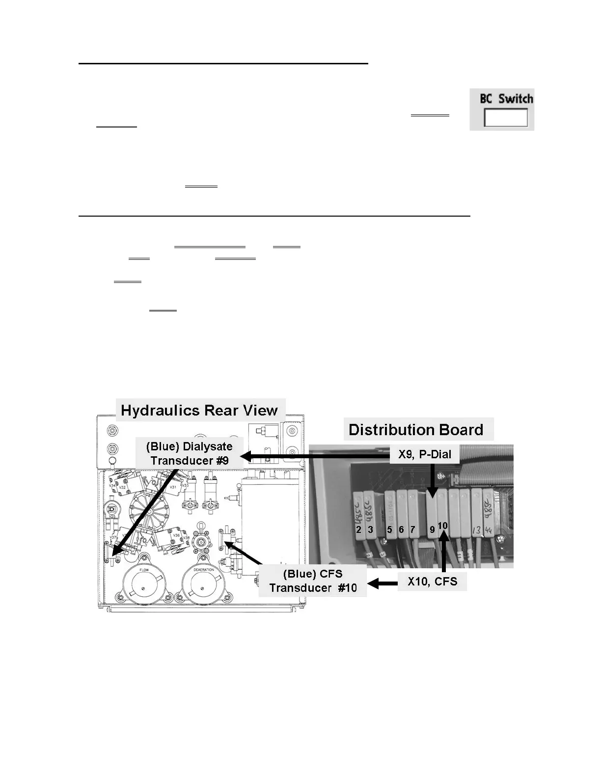
a) Figure below, CAREFULLY trace BOTH wire harnesses from distribution board connectors “X9,
P-Dial” AND “X10, CFS” to ENSURE they go to the correct (blue) Pressure Transducer.
b) Are BOTH Pressure Transducers connected properly?
Yes BOTH are connected properly! See procedure number F- 5.2.0 (page 57).
No Connect them properly i.e. CFS #10 → “X10, CFS”; Dialysate Pressure #9 → “X9, P-Dial”
and allow one (1) minute. Call debug screen 1 to watch Flow Error for four (4) minutes. If it
remains = 0 this may have fixed the problem. If it EVER = 1, even just once, continue
procedure number F- 5.2.0 (page 57)
Figure 10 – Pressure Sensors

 Loading...


