2008T Troubleshooting Guide
P/N 490292 Rev. A
T- 1.0.17 SIMULATE CONDUCTIVITY
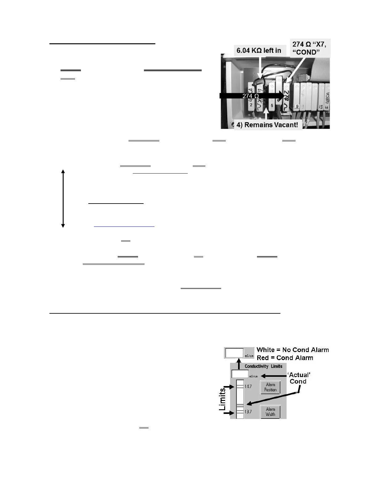
a) Figure right, leaving the 6.04 KΩ resistor in, plug the
274 Ω resistor plug, from the TWO-RESISTOR
SET into the Cond Cell’s distribution board position,
“X7, COND”.
b) Watch the [Conductivity] window for one (1) minute.
THREE (3) possible scenarios 1) or 2) or 3) below:
1) IF (and ONLY if) BETWEEN 12.9 and 14.5 mS AND is stable (i.e. does NOT change more
than 0.2): See procedure number T- 1.0.18 (page 248).
2) IF (and ONLY if) BETWEEN 12.9 and 14.5 BUT changes MORE than 0.2: THREE (3) possible
bad components (see COMPONENT LIST below). Turn the machine off and swap in each, one at a
time, in between returning to Dialysis Program, until [Conductivity] is STABLE between 12.9 and
14.5 mS.
COMPONENT LIST: 1) Sensor Board
a
; 2) Power Logic Board; 3) Functional Board
a
.
a
To prevent “Cond Offset Failure”
place the machine in T and C Mode (refer to
OPERATING MODES, page 19))
3) IF less than 12.9 OR more than 14.5 mS: See parts a AND b below:
a) Remove the 274 Ω plug then reinsert it OR consider using the 274 Ω plug from a different
TWO-RESISTOR SET.
b) If (and ONLY if) [Conductivity] is still is less than 12.9 OR more than 14.5 proceed to page
320
, procedure number T- 7.0.0. If NOW STABLE between 12.9 and 14.5 see procedure
number T- 1.0.18 (page 248).
T- 1.0.18 CONDUCTIVITY IS BETWEEN 12.9 AND 14.5 / VERIFY CONDUCTIVITY
Based on the [Conductivity] window’s color, TWO (2) possible scenarios:
1) IF (and ONLY if) pale / yellow white: See procedure number T- 1.0.19 (page 249).
2) IF RED: See parts a THROUGH d below:
a) At the bottom of the screen, press the ‘Dialysate’
tab (Figure right).
b) If necessary, adjust the Limits until the ‘Actual’
Conductivity CENTERED is between them.
c) Press ‘Enter’!
d) Allow three (3) minutes OR until if the [Conductivity] window turns white. TWO (2) possible
scenarios next page:

 Loading...


