2008T Troubleshooting Guide
P/N 490292 Rev. A
P- F.4.0 BOTH +12 AND +5 VDC LOW / ISOLATE 24 VOLTS DC AT POWER LOGIC BOARD
a) ENSURE the machine is on (fan running)!
b) CAUTION! DC voltages (V
DC
) are about to be measured at pins that are VERY close to others and
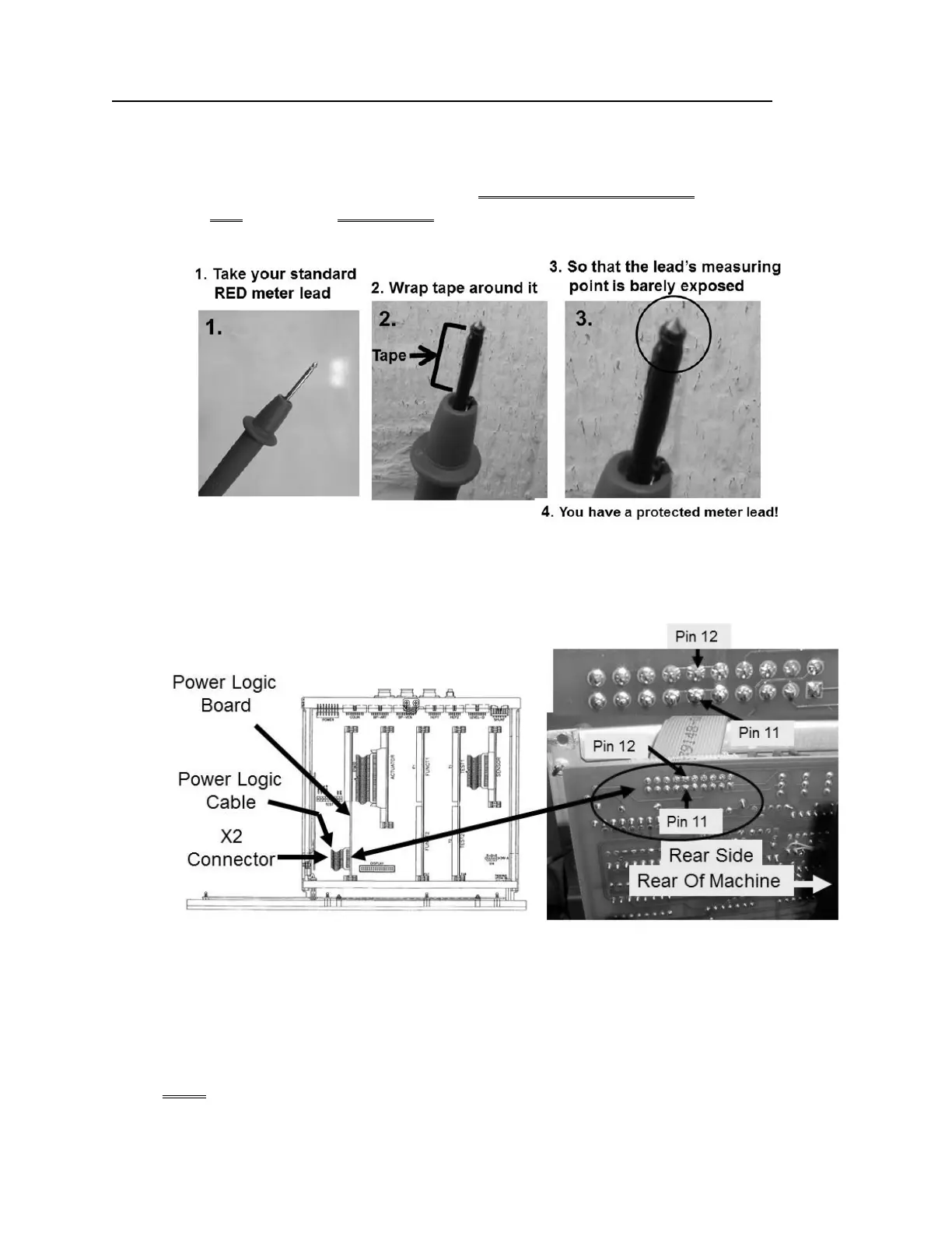
touching pins together with a standard meter lead could cause massive DAMAGE! As directed below
make your RED meter lead a PROTECTED lead! DO NOT CONTINUE UNTIL YOU
HAVE DONE THIS!
c)
ENSURE the meter’s black lead REMAINS connected to chassis ground!
d) Figure below, at the top edge of the Power Logic Board, closest to the screen, locate its 20-pin X2 ribbon
cable.
Figure 115 – Power Logic Board Pins 11/ 12 / 13
e) TWO (2) measurements at the rear side of the X2 cable:
MEASUREMENT #1: At pin 12 (TOP row, 6 pins from the REAR of machine)
MEASUREMENT #2: At pin 11 (BOTTOM row, 6 pins from the REAR of machine)
f) Are BOTH more than 23.0 volts DC?

 Loading...


