2008T Troubleshooting Guide
P/N 490292 Rev. A
UF- 6.0.0 CHECK UF PUMP FUNCTION
a) Place the machine into RINSE and ENSURE the external
flow indicator’s ‘bob’ is moving up and down.
b) Ensuring NO LEAKS, per the Figure right, remove the
Ultrafiltrate Output Sample Connector from its port to
observe UF Pump output.
c) Are there ‘strong individual pulses’ through the Fluid Sample
Connector that ‘squirt’ into the room at least six (6) feet?
Yes Strong pulses! See procedure number UF- 6.1.0
(page 554).
No Weak or no pulses! Swap in the listed components (see Component List below), one at a time,
and in between, to see if the new component fixes the problem, return to (ABOVE) procedure
number UF- 6.0.0 (
page 554).
Component List: 1) UF Pump
1
;
2) Actuator-Test Board
2
; 3) Actuator cable
3
; 4) Distribution
board; 5) Motherboard.
1
Without mounting the pump into the cabinet YET, plug a known good pump into
distribution board position “P22, UF-P”.
2
Turn the machine OFF before swapping in a known good Actuator-Test Board.
3
The Actuator cable can be checked. NOTE that four (4) UF PUMP connections will be
checked and proceed to page 566, SECTION 16 - CHECKING THE ACTUATOR BOARD
CABLE
UF- 6.1.0 STRONG PULSES / ISOLATE UF PUMP CONSISTENCY
a) Place the machine into Service Mode → Calibrate Hydraulics → UF
Pump Volume.
b) Follow the screen’s instructions through step #4. The screen’s
[Target] box defaults to 24 strokes. DON’T CHANGE IT!
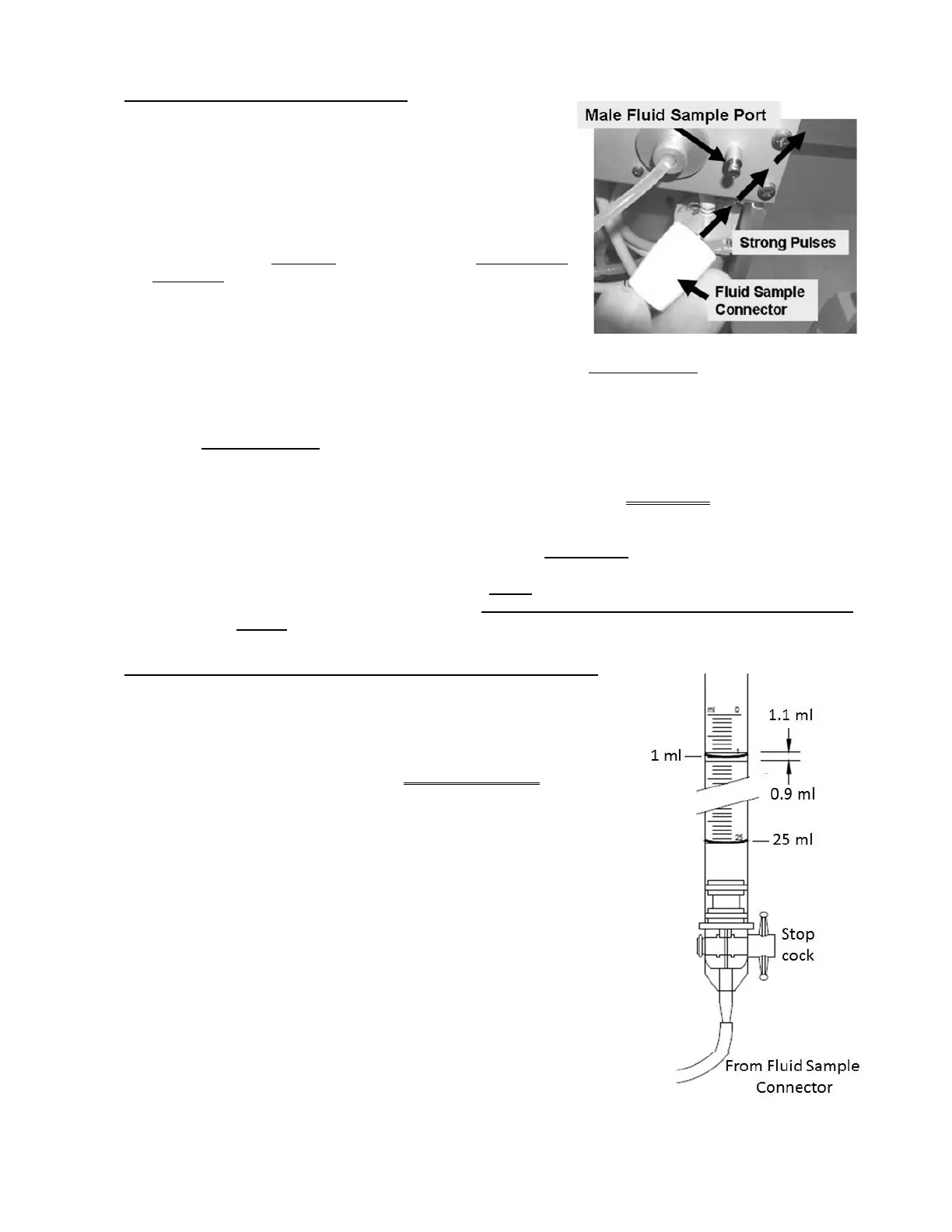
c) Per the Figure right, attach the Fluid Sample Connector to a 25 ml
burette. Ensure the burette’s stopcock is OPEN!
d) Press ‘Prime’ and allow the [Target] box to reach 0.
e) Drain the burette to EXACTLY the 25 ml scale mark.
f) REPEAT parts c and d. Does burette volume read between the 0.9
and 1.1 ml scale i.e. UF Pump delivered between 23.9 and 24.1 ml?
Yes Between 23.9 and 24.1 ml! Return to (ABOVE) procedure
number UF- 2.1.0
(page 550).
No Referring to Figure 86 (page 550), attempt to calibrate UF
Pump volume. Does it calibrate to between 23.9 and 24.1 ml
after 24 strokes?

 Loading...


