2008T Troubleshooting Guide
P/N 490292 Rev. A
P- H.4.5 ISOLATE +24 VOLT- A
a) ENSURE the black lead remains attached to ground!
b) ENSURE the machine is ON (fan running)!
c)
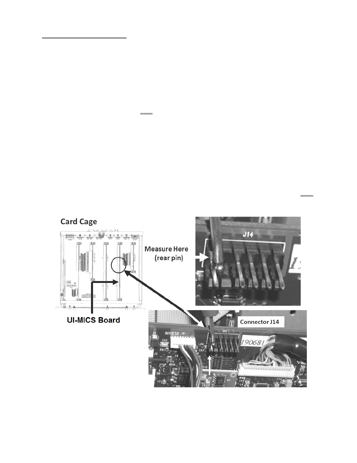
Figure below, locate the UI-MICS board’s ‘J14’ connector at the top edge of the UI-MICS board.
d) Place the red meter lead onto the ‘J14’ pin AS SHOWN below. TWO (2) possible scenarios:
Scenario #1: IF (and ONLY if) NOT between 23.0 and 28.0 volts DC (V
DC
): Proceed to page 708,
procedure number P- 4.0.0.
Scenario #2: IF between 23.0 and 28.0 volts DC (V
DC
). TWO (2) possible scenarios 1) or 2) below:
1) IF (and ONLY if voltage alarm has NEVER occurred but “Failed Sending
Data…” has: The most likely culprit is the Actuator-Test Board HOWEVER if
Failed Sending Data…” reoccurs any one of the card cage boards may be
interfering with the communication between the Actuator-Test and the Functional
Boards.
2) ALL OTHER scenarios: A) To measure voltage over a period of time now CLIP the
red meter lead onto the ‘J14’ pin; B) See procedure number P- H.4.6 (page 684).
Figure 119 – UI-MICS Board Connector J14 / +24V-A

 Loading...


