2008T Troubleshooting Guide
P/N 490292 Rev. A
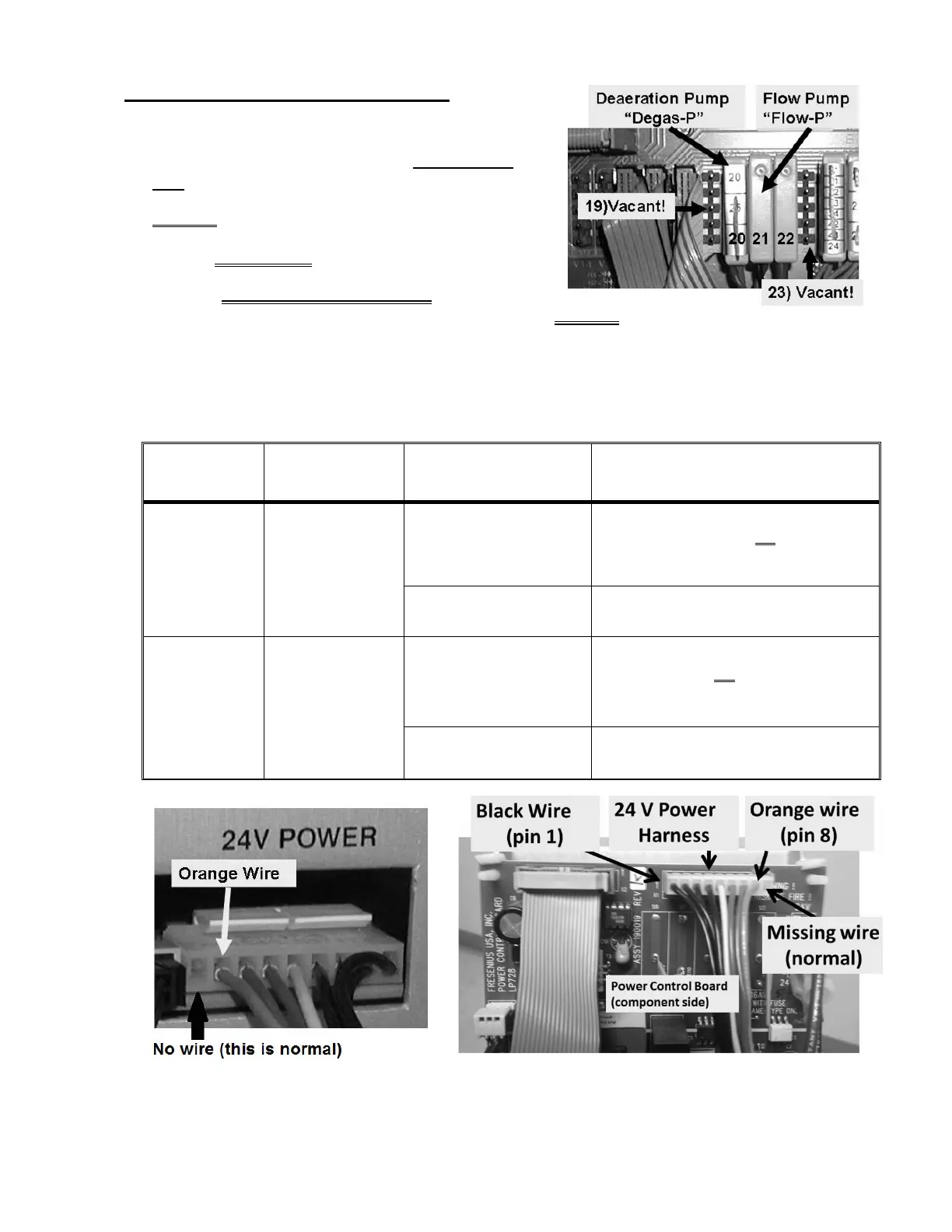
MOTORS- 4.6.0 ISOLATE MOTOR VOLTAGE
a) Figure right, avoiding the VACANT positions on the left
and right, return the motor connector,
without the
cap, to its distribution board position.
b) ENSURE the connector is aligned properly!
c) Set your CALIBRATED volt meter to DC voltage (V
DC
).
d) Measure, inside the distribution board, between the
terminals where the wires are soldered. IMPORTANT! ENSURE good contact with BOTH
terminals!
e) Per Table 5 below, perform the indicated Response based on measured voltage.
Table 5 – Motor Troubleshooting
MOTOR
DISTRIBUTION
BOARD
POSITION
DC VOLTAGE
READING
Your RESPONSE
DEAERATION P20, “DEGAS-P”
15 volts DC or more
TWO (2)
possible bad components:
1) Bad deaeration motor OR
2) Intermittent 24V Power Harness
connection. See Figure below.
Less than 12 volts DC
Bad motor voltage! See procedure number
MOTORS- 4.7.0 (page 148)
FLOW P21, “FLOW-P”
5 volts DC or more
TWO (2)
possible bad components:
1) Bad flow motor OR
2) Intermittent 24V Power Harness
connection. See Figure below.
Less than 5 volts DC
Bad motor voltage! See procedure number
MOTORS- 4.7.0 (page 148)
24V Power Harness (Behind the card cage / Inside the Power Supply)

 Loading...


