2008T Troubleshooting Guide
P/N 490292 Rev. A
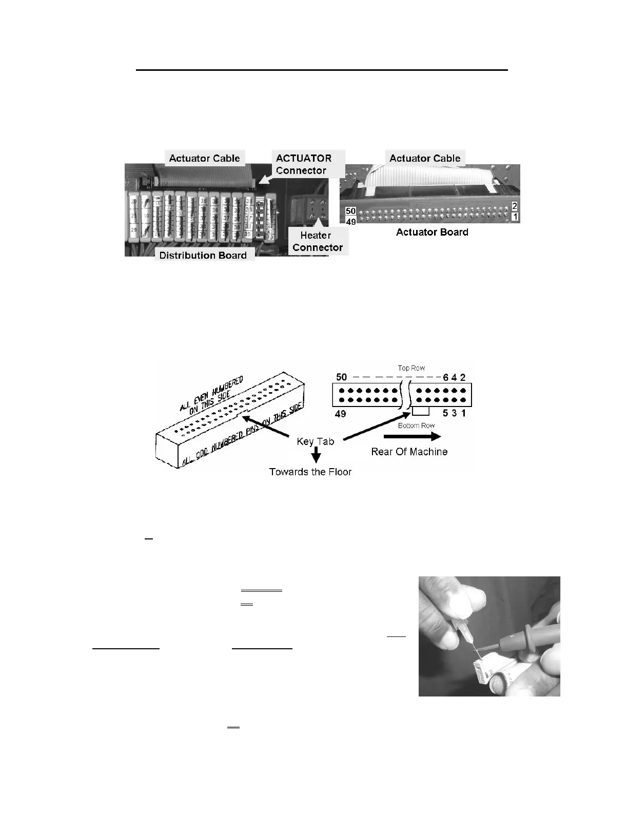
SECTION 16 - CHECKING THE ACTUATOR BOARD CABLE
The 50-conductor actuator cable runs between the distribution board and the Actuator-Test Board. Check
ONLY the NOTED above component connection(s)!
a) Per the Figure below, this procedure checks the cable by measuring conductor resistance (Ω) from one
end (distribution board) to the other (Actuator-Test Board). Good conductors measure 2 Ω or less.
b)
IMPORTANT! Turn the machine OFF and open the card cage!
c) Check the cable’s entire length (distribution board to Actuator-Test Board) for bare wires or other damage!
d) Per the Figure above, unplug the cable from the distribution board’s ACTUATOR connector. Check inside
the vacant ACTUATOR connector for ‘white’ corrosion or damaged male pins. Damage ANYWHERE
may be the problem!
Figure 91 – Female Distribution Board Connector
e) To determine your ohm (Ω) meter’s internal resistance touch the leads together. The meter MUST read
less than 1 Ω! Subtract the reading from ALL subsequent measurements!
f) Per the Figure above, the cable’s female connector has two rows of PLUGS. Hold it with its KEY TAB
DOWN. This puts the even numbered PLUGS in the top row AND the ‘Rear of Machine’ to the right.
g) Refer to Table 12 (page 567), to LOCATE the appropriate numbered
PLUG(S) for the NOTED PUMP or the NOTED VALVE Table 13
(page 568).
h) A meter probe will NOT penetrate deep enough and a paper clip may
cause damage! Use 25 gauge non-stranded wire as a ‘probe’. Per the
Figure (right), insert the ‘probe’ into the appropriate PLUG, then place
(or clip) one of the meter leads onto it.
i) Per Figure 92 (page 567), the cable terminates at the actuator
board’s P2 connector. The rear side PINS are in two rows. Odd
numbered in the bottom row, even in the top. NOTING the reference to the ‘Rear of Machine’ locate the
appropriate PIN per Table 12 or Table 13.

 Loading...


