2008T Troubleshooting Guide
P/N 490292 Rev. A
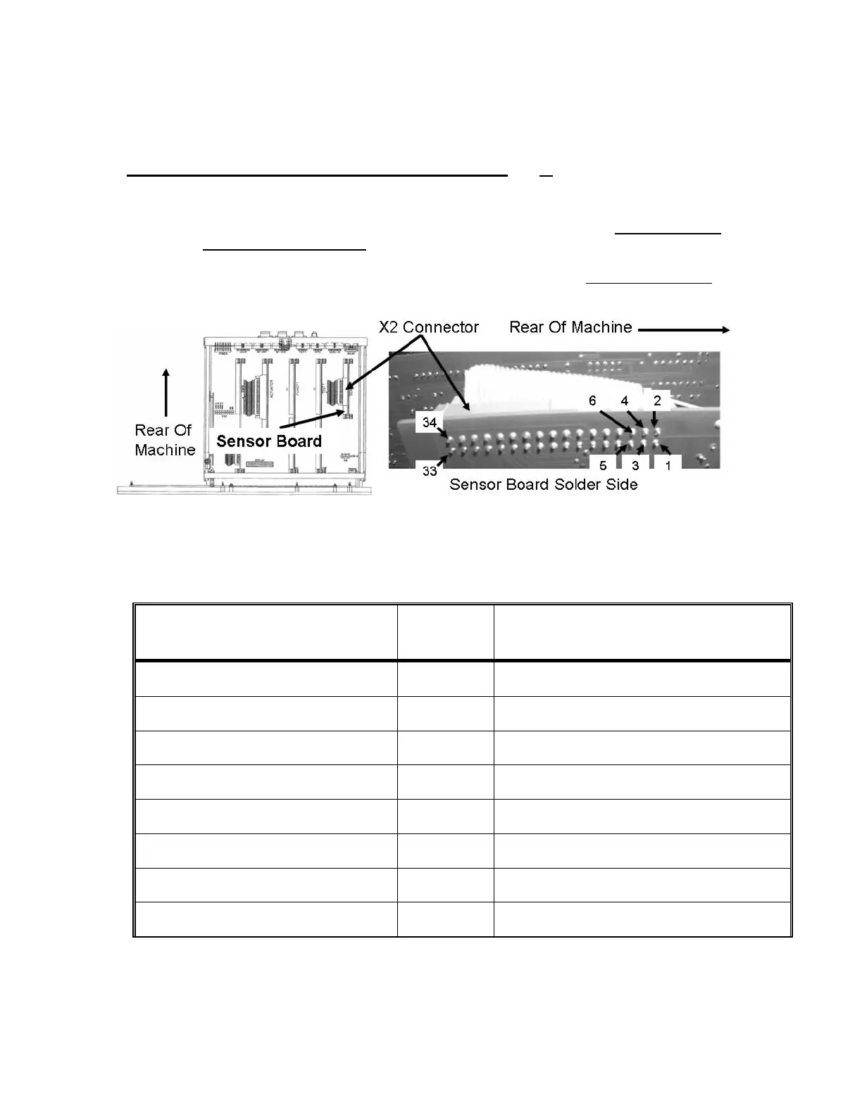
i) Per the Figure below, the cable terminates at the Sensor Board’s X2 connector. The solder (rear) side
PINS are in two rows. Odd numbered in the bottom, even numbered in the top. NOTING the reference
to the ‘Rear of Machine’ locate the appropriate PIN number per Table 14 (page 570
j) Place the second meter on the matching numbered PIN on the solder (rear) side of the P2 connector.
Some components require checking multiple conductors. 2.0
Ω or less for ALL required
conductors?
Yes The cable is good! Return it to the distribution board. If referred to CHECKING THE
SENSOR BOARD CABLE, return to the procedure that brought you here as noted.
No Unplug the cable from the Sensor Board’s X2 connector. Check inside the connector for
damaged male pins. If the pins are okay, replace the cable.
Figure 94 – Electronic Card Cage (Sensor Board)
Table 14 – Cable Plug / Sensor Board X2 Pin Locations
Table 14 continued next page
HYDRAULIC COMPONENT
Cable Plug
/ X2 PIN #
Cable Plug / X2 PIN LOCATION
NTC #3 12 Top row, 6 pins from the rear of machine
NTC #2 13 Bottom row, 7 pins from the rear of machine
FLOAT 21 Bottom row, 7 pins from the front of machine
CFS TRANSDUCER (1 of 3) 11 Bottom row, 6 pins from the rear of machine
CFS TRANSDUCER (2 of 3) 14 Top row, 7 pins from the rear of machine
CFS TRANSDUCER (3 of 3) 15 Bottom row, 8 pins from the rear of machine
COND CELL 16 Top row, 8 pins from the rear of machine
ACID EOS 25 Bottom row, 5 pins from the front of machine

 Loading...


