2008T Troubleshooting Guide
P/N 490292 Rev. A
2) IF (and ONLY if) BOTH valves between 40 and 100 Ω: See procedure number DVF- 4.2.0 (page
717).
3) IF ONE OR BOTH is less than 40 OR more than 100 Ω: Replace the valve AND its blue wiring
harness.
DVF- 4.2.0 BOTH VALVES BETWEEN 40 AND 100 Ω / ISOLATE TOTAL CIRCUIT RESISTANCE (Ώ)
a) Return BOTH valves connectors to their PROPER distribution board positions!
b) GENTLY open the card cage!
c)
Connect the volt meter’s black lead to chassis ground (see Figure 2 (page 4)).
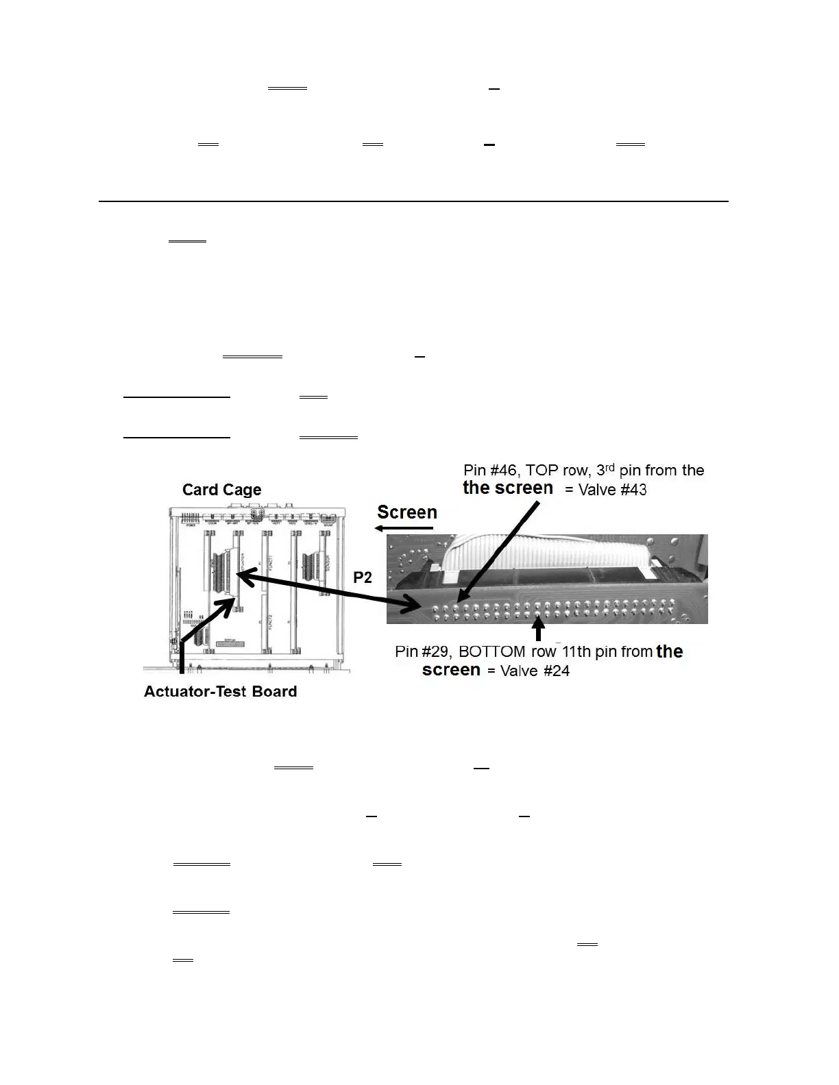
d) Figure below, TWO (2) measurements below, from the solder (rear) side of the Actuator-Test board’s P2
connector. Both should be between 40 and 100 Ω!
Measurement #1: Pin #46 (TOP row, 3rd pin from the screen) = Valve #43
Measurement #2: Pin #29 (BOTTOM row, 11th pin from the screen) = Valve #24
e) TWO (2) possible scenarios:
1) IF (and ONLY if) BOTH are between 40 and 100 Ω: See procedure number DVF- 4.2.2 (page
718).
2) IF ONE OR BOTH LESS THAN 40 Ω OR MORE THAN 100 Ω: Perform parts a THROUGH c
below:
a) ENSURE the machine was OFF AND valves #24 and #43 were returned to the distribution board
properly! If NOT, return to (ABOVE) procedure number DVF- 4.2.0 (page 717).
b) ENSURE both measurements were made at the correct Actuator-Test Board P2 pins!
c) THREE (3) possible bad components: 1) Bad Actuator-Test Board OR; 2) Bad actuator cable
OR; 3) Bad distribution board.

 Loading...


