2008T Troubleshooting Guide
P/N 490292 Rev. A
VOLTAGE DETECTOR CALIBRATION
A) Per the Figure below, the EXTENDER BOARD (P/N 190600) is required.
B) Turn the machine OFF and GENTLY open the card cage!
C) Behind the card cage, ENSURE the 24V POWER cable remained plugged in!
D) To avoid error, per the figure below:
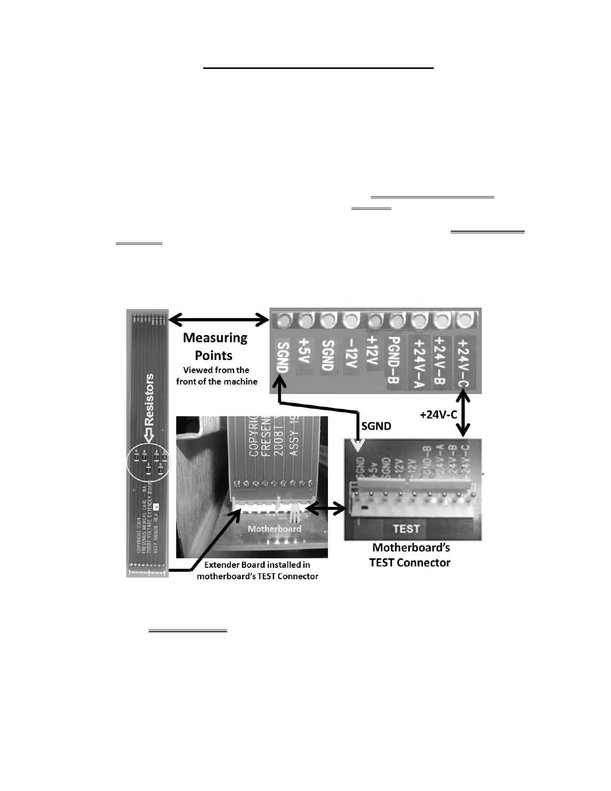
1) Keeping the EXTENDER BOARD’S resistors towards the FRONT OF THE MACHINE install it into
the motherboard’s nine (9) pin TEST* connector. *To LOCATE refer to Figure 4A (page 10)).
2) ENSURE the board is matched pin for pin to the TEST connector! From the FRONT OF THE
MACHINE SGND on the LEFT; 24V-C on the RIGHT!
3) Push the board down hard. It may resist a good connection into the motherboard.
4) Pull up on the board. If installed correctly it resists pulling out!
E) Enter Service Mode → Calibrate Monitor → Voltage Detection.
F)
Set your CALIBRATED volt meter to volts DC (V
DC
).
G) Connect the meter’s black lead to chassis ground (refer to Figure 2, page 4).
H) Measure at the Extender Board’s +12V measuring point (five (5) pins from the left).
Parts I through P next page

 Loading...


