2008T Troubleshooting Guide
P/N 490292 Rev. A
P- 2.0.5 ISOLATE POWER LOGIC CABLE
a) CAUTION! Signals are about to be measured at pins that are VERY close to others and touching
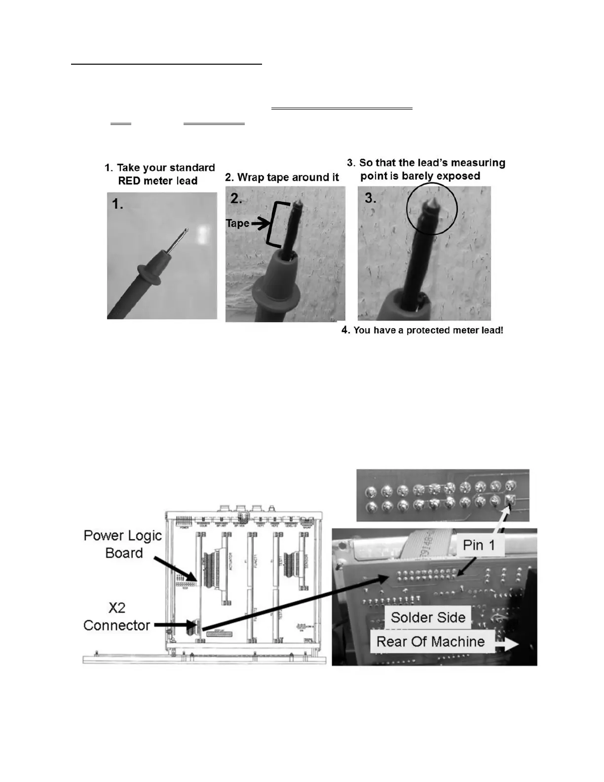
them together with a standard meter lead MAY CAUSE massive damage! As directed below, make
your RED meter lead PROTECTED! DO NOT CONTINUE UNTIL YOU HAVE DONE
THIS!
b)
Per the Figure below, at the top of the Power Logic Board, closest to the screen, locate its 20-pin
‘X2’ ribbon cable.
c) Measure at the rear (solder) side of the X2 connector at
pin 1 (bottom row, first pin from the REAR of
the machine). More than 10.0 volts DC?
Yes More than 10 volts! See procedure number P- 2.0.6 (page 703).
No Less than 10 volts! Replace the 20-pin Power Logic X2 ribbon cable.
Figure 130 – Electronic Card Cage / Power Logic Board / Pin1

 Loading...


