2008T Troubleshooting Guide
P/N 490292 Rev. A
CO- 10.0.60 ISOLATE POST SENSORS STABILITY
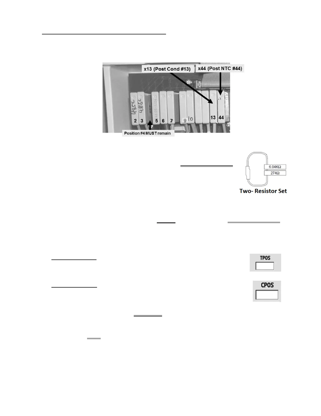
a) Per the Figure below, remove Post Dialyzer Temp Sensor NTC #44’s connector from distribution board
position “x44, NTC-POST”.
b) Using a flashlight, check the “x44” position for ‘white’ corrosion and / or damaged male pins. If
damage is located this may be the problem!
c) Per the Figure right, place the
6.04 KΩ plug, from the TWO-RESISTOR SET
into the Post Dialyzer Temp Sensor’s distribution board position “x44, NTC-
POST”.
d) Per the Figure above, remove Post Dialyzer Cond Cell #13’s connector from
distribution board position “x13, COND-POS”.
e) Check the “x13” position for ‘white’ corrosion and / or damaged male pins.
f) Leaving the 6.04 KΩ plug installed, place the
274 Ω resistor plug, from the TWO-RESISTOR SET,
into Post Dialyzer Cond Cell’s #13’s distribution board position “x13, COND-POS”.
g) Call debug screen 5. TWO (2) checks then proceed according to the TWO (2) scenarios after check
#2:
CHECK #1 (TPOS): WITHOUT LOOKING AWAY, watch TPOS for one (1) minute
noting its highest and lowest values. Subtract the lowest value seen from the
highest. Two (2) or less = GOOD! More than two (2) = BAD!
CHECK #2 (CPOS): Now watch CPOS for one (1) minute noting its highest and
lowest values. Subtract the lowest value seen from the highest. Eight (8) or less =
GOOD! More than eight (8) = BAD!
1)
IF (and ONLY if) TPOS AND / OR CPOS ARE ‘BAD’: Proceed to page 432,
procedure number CO- 11.0.00.
2)
IF TPOS AND CPOS are ‘GOOD’: See parts a through d below:
a) Return Post Dialyzer Temp Sensor NTC #44’s connector to position “x44, NTC-POST”.
Parts b through d next page

 Loading...


