2008T Troubleshooting Guide
P/N 490292 Rev. A
LEAKING- 3.3.0 LEAK BETWEEN FLOW PUMP AND BALANCING CHAMBER VALVES #36 or #38
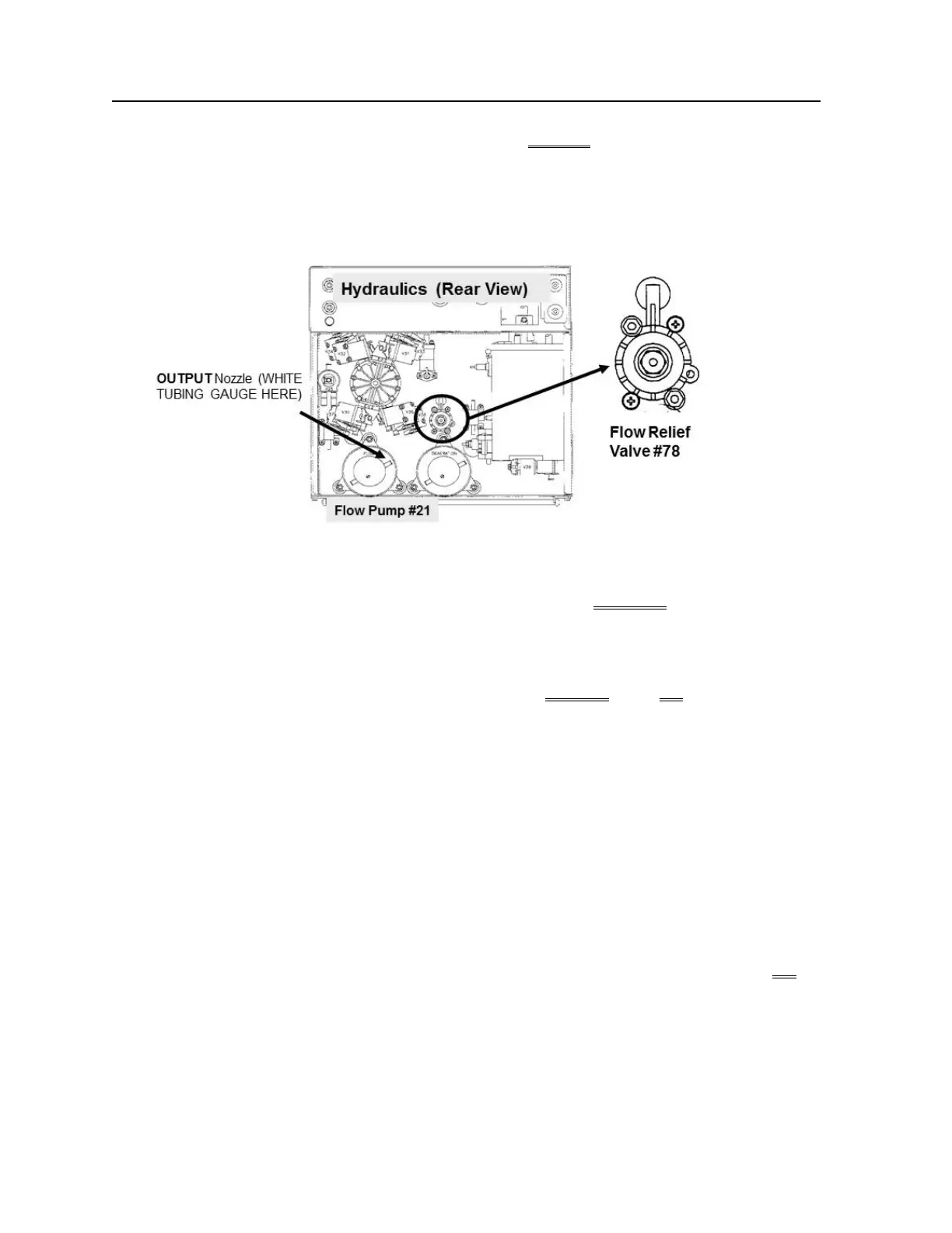
a) Secure the tubing clamps at Valves #36* and #38*. * To LOCATE these Valves refer to the Figure
previous page!
b) A psi gauge is used next. ENSURE it reads 0 psi before installing it!
c) Per the Figure below, install the gauge at the Flow Pump’s OUTPUT (white) tubing.
d) Tie wrap both side of the gauge tubing to prevent leaks and false readings.
e) Enter Service Mode → Calibrate Hydraulics → Flow Pressure but DO NOT follow the screen’s
instructions!
f) While watching the gauge, press ‘Enter’ ONCE.
g) Normal pressure is between 35 and 36 psi. Does pressure EXCEED 38 psi OR ‘peg’ its needle i.e. much
more than 38 psi?
Yes More than 38 psi! Per the Figure above, turn Valve #78’s nut COUNTERCLOCKWISE
(outward) attempting to adjust to between 35 and 36 psi. If it will not adjust Valve #78 may
be bad.
No Between 29 and 38 psi. TWO (2) possible scenarios:
1) IF (and ONLY if) Flow Relief #78 is leaking from its body! Tighten the Phillips
screws on the Valve body then watch for four (4) minutes. If the leak continues
replace Valve #78 and calibrate it.
2) IF Flow Relief Valve #78 is NOT leaking! If the leak continues, there may be a bad
O-ring seal between the Balancing Chamber and Valve #36 and/or #38 OR Valve
#36 and / or #38 valve body is cracked.

 Loading...


