February 2013
4-256
ColorQube® 9303 Family
REP 62.9, REP 62.10
Repairs/Adjustments
REP 62.9 Input Module Angle Sensor
Parts List on PL 62.15
Removal
WARNING
Switch off the electricity to the machine. Refer to GP 14. Disconnect the power cord
from the customer supply while performing tasks that do not need electricity. Electricity
can cause death or injury. Moving parts can cause injury.
WARNING
Take care during this procedure. Sharp edges may be present that can cause injury.
1. Remove the scanner top cover, REP 62.2.
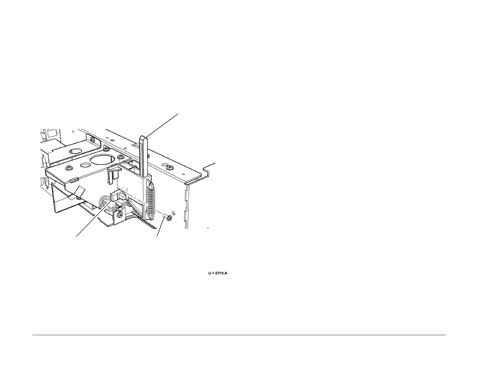
2. Figure 1, remove the input module angle sensor.
Figure 1 Input module angle sensor
Replacement
1. Reverse the removal procedures to replace the input module angle sensor.
2. When replacing the input module angle sensor, ensure that the lugs on the sensor are
located in the slot of the frame before tightening the screw.
REP 62.10 LED Exposure Lamps
Parts List on PL 62.15
Removal
WARNING
Switch off the electricity to the machine. Refer to GP 14. Disconnect the power cord
from the customer supply while performing tasks that do not need electricity. Electricity
can cause death or injury. Moving parts can cause injury.
WARNING
Take care during this procedure. Sharp edges may be present that can cause injury.
1. Remove the CVT glass, REP 62.3.
2. Remove the CVT ramp and document glass assembly REP 62.3.
3. Figure 1. Remove the LED exposure lamp(s).
1
Remove one screw.
2
Depress the actuator
to release the sensor.
3
Disconnect the sensor from
the harness and remove.
 Loading...


