February 2013
4-111
ColorQube® 9303 Family
REP 12.9-110, REP 12.10-110
Repairs/Adjustments
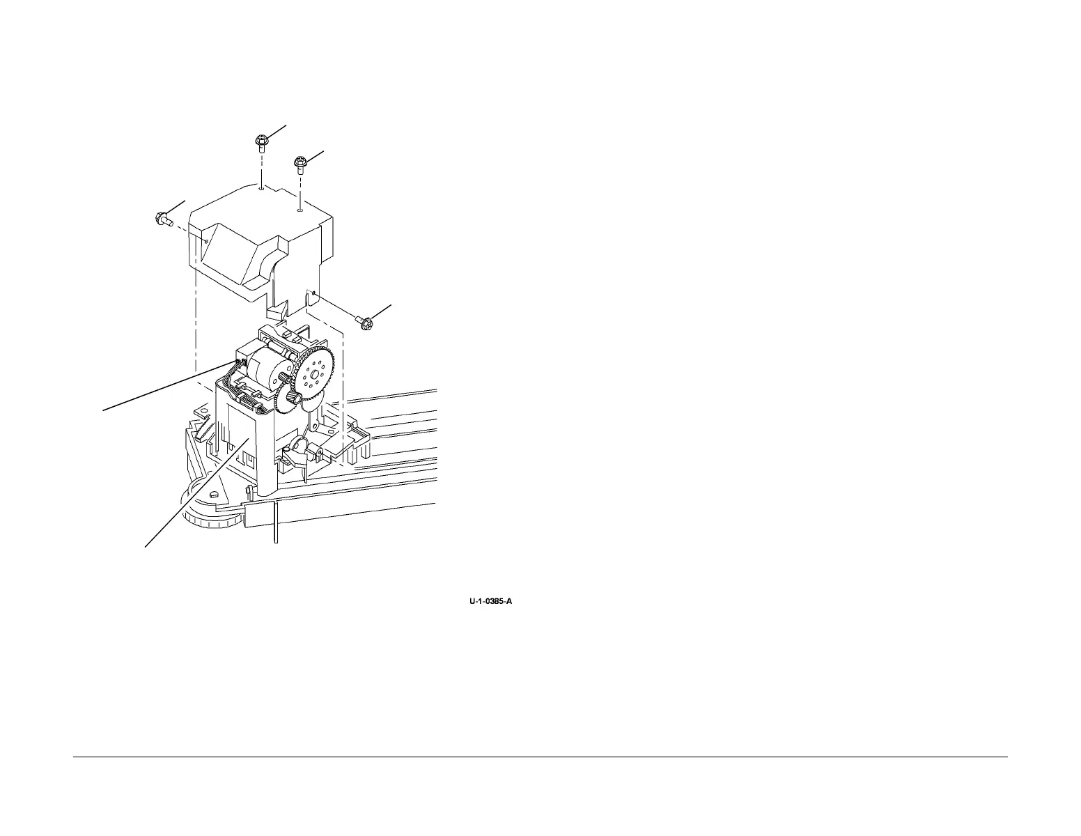
3. Remove the staple head unit from the stapling unit Figure 1.
Figure 1 Removing the staple head unit
Replacement
Reverse the removal procedure to replace the staple head unit.
REP 12.10-110 Ejector Assembly Sensors
Parts List on PL 12.50.
Removal
WARNING
Switch off the electricity to the machine. Refer to GP 14. Disconnect the power cord
from the customer supply while performing tasks that do not need electricity. Electricity
can cause death or injury. Moving parts can cause injury.
WARNING
Take care during this procedure. Sharp edges may be present that can cause injury.
WARNING
Take care not to topple the LCSS. The LCSS is unstable when un-docked from the
machine. Do not show the customer how to un-dock the LCSS.
1. Disconnect the two harnesses between the LCSS and the machine.
2. Un-dock the LCSS, REP 12.13-110 and move it away from the machine.
3. Ensure the stapling unit is at the home position.
4. If necessary, manually move the ejector to the left position.
3
Remove the staple head unit.
1
Remove 4 screws
marked A then
remove the stapler
cover.
2
Disconnect the
harnesses.
A
A
A
A
 Loading...


