February 2013
4-272
ColorQube® 9303 Family
REP 75.1, REP 75.2
Repairs/Adjustments
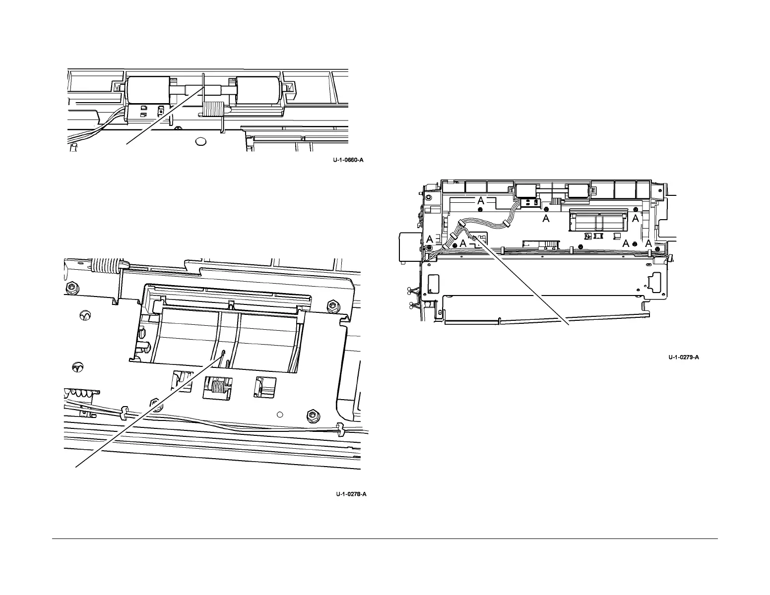
3. Make sure that the housing spring is positioned on top of the takeaway idler roller shaft
when the upper feed assembly top cover is installed, Figure 4.
Figure 4 Spring position
4. Check that the correct screw is used to attach the upper feed assembly top cover.
5. Make sure that the torsion chute spring is positioned on top of the chute upper insert, Fig-
ure 5.
Figure 5 Spring position
6. Check that the harness routing is correct, Figure 1.
REP 75.2 Tray 5 Stack Height Sensor
Parts List on PL 81.45
Removal
WARNING
Switch off the electricity to the machine. Refer to GP 14. Disconnect the power cord
from the customer supply while performing tasks that do not need electricity. Electricity
can cause death or injury. Moving parts can cause injury.
WARNING
Take care during this procedure. Sharp edges may be present can cause injury.
1. Remove the top cover, REP 75.8.
2. Prepare to remove the tray 5 stack height sensor, Figure 1.
Figure 1 Preparation
3. Remove tray 5 stack height sensor, Figure 2.
Housing spring position
Position the torsion chute spring on the
top of the chute.
1
Disconnect the harness
 Loading...


