February 2013
6-101
ColorQube® 9303 Family
GP 36, GP 37
General Procedures/Information
GP 36 How to Unlock the Cleaning Unit
Purpose
To manually unlock and release the cleaning unit.
Procedure
WARNING
Take care during this procedure. Sharp edges may be present that can cause injury.
1. Open the front door.
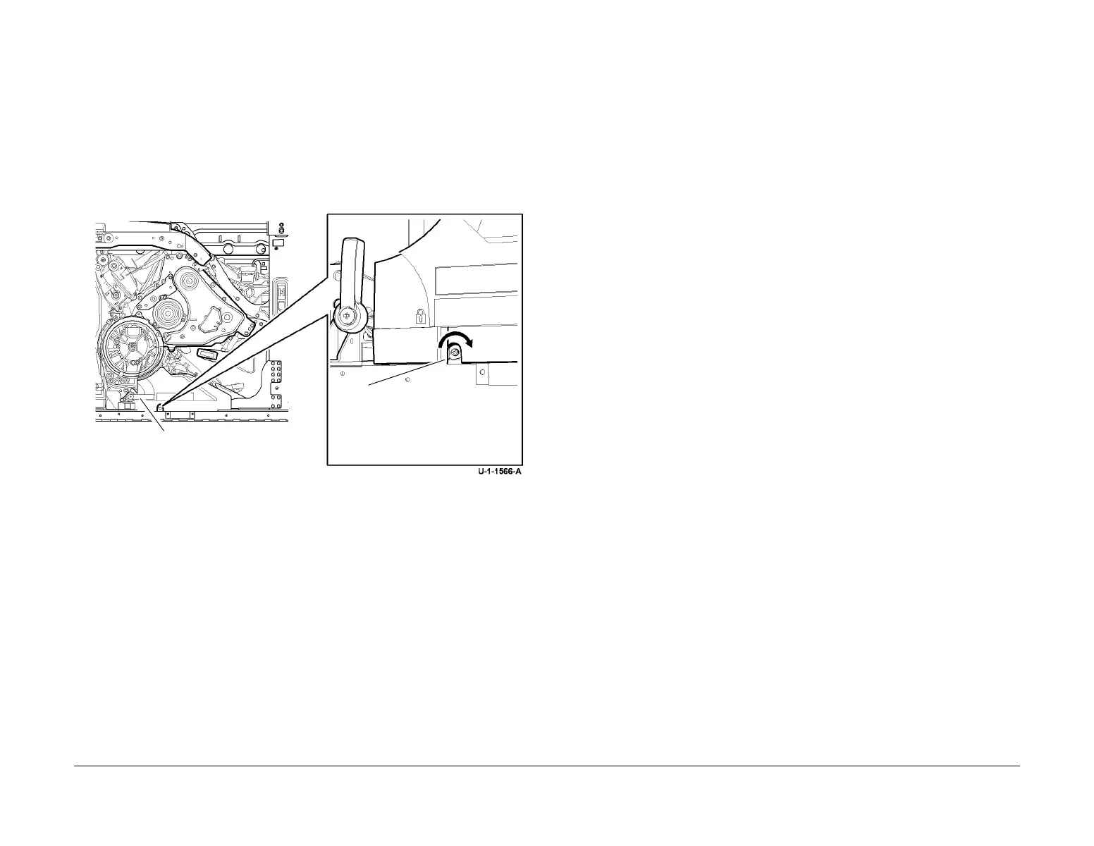
2. Unlock the cleaning unit, Figure 1.
Figure 1 Unlock the cleaning unit
GP 37 Post Part Replacement Routines
Use this procedure to determine which service mode routines to run after a part reinstallation
or replacement.
Go to the relevant part:
• Printhead (New Head)
• Printhead (Original Head Reinstalled)
• Umbilical Assembly (Original Head Reinstalled)
• Upper Carriage Assembly (Original Head Reinstalled)
• Lower Carriage Assembly (Original Head Reinstalled)
• X Axis Drive Motor
• Stitch Roll Motor
• Stitch Roll Motor Lead Screws
• Purge Line Filter
• Reservoir
• Drum
• Front Drum Frame Assembly
• Drum Drive Motor
• Drum Position Encoder
• Drum Pulley
• IOD Assembly
• Front Guide Track
• Rear Guide Track
• Registration/Pre-heat Assembly
• Horizontal Paper Path Assembly
Printhead (New Head)
Refer to PL 91.20 Item 2 and PL 91.25 Item 2.
Perform the following procedures in the order shown:
1. dC972 Printhead Uniformity. Select Option 1. Select the manual procedure and all 4 print-
heads.
2. dC131. Check the following NVM values:
• 490-020. The value must be 0. If necessary change the value to 0.
• 490-021. If the value is 2, change the value to 1. If the value is 0, 1 or 3, do not
change the value.
Printhead (Original Head Reinstalled)
Refer to PL 91.20 Item 2 and PL 91.25 Item 2.
Perform the following procedures in the order shown:
1. dC967 Head to Drum Spacing Check.
2. dC971 Head to Head Alignment Adjustment.
3. dC972 Printhead Uniformity:
• Option 3 Head to Head Uniformity
• Option 4 TRC Generation
1
Move the handle to the
unlock position.
2
Insert a flat blade screwdriver
into the cutout. Slowly rotate the
screwdriver and gently pull the
cleaning unit.
 Loading...


