February 2013
4-333
ColorQube® 9303 Family
REP 91.8, REP 91.9
Repairs/Adjustments
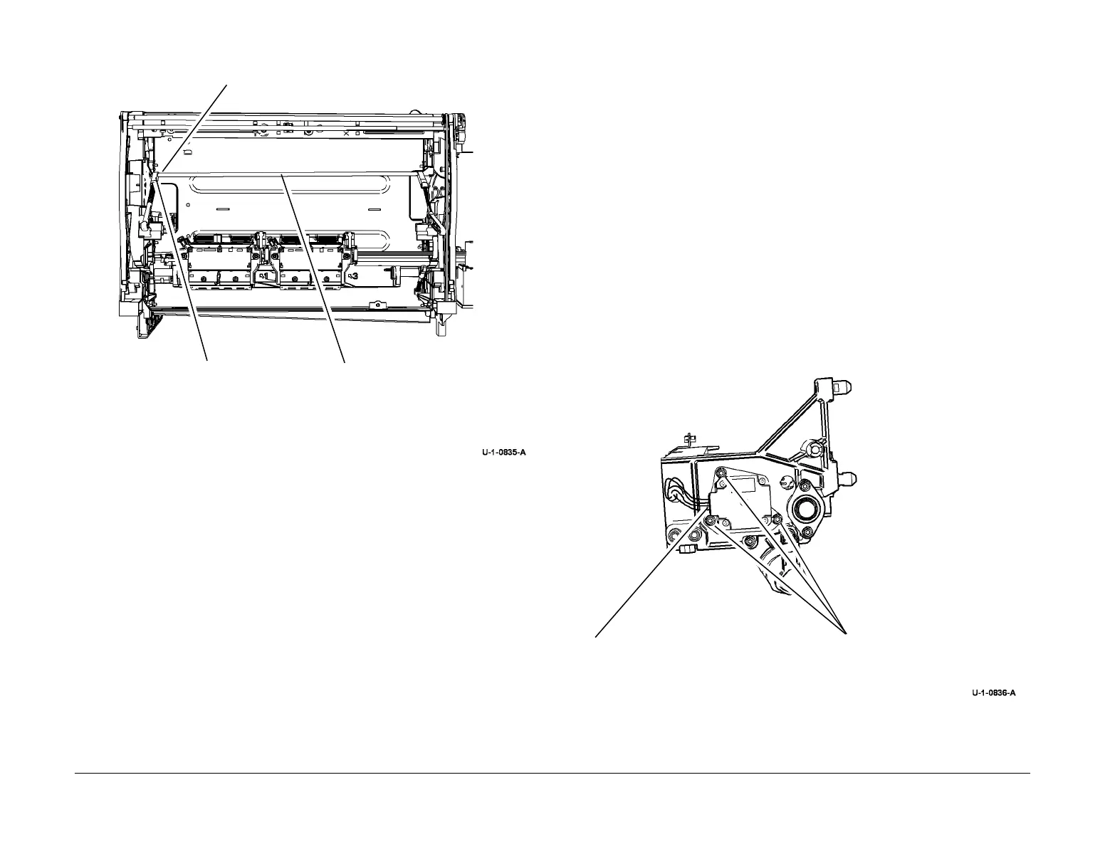
4. Remove the upper carriage drive shaft, cranks and compliant links, Figure 2.
Figure 2 Drive shaft assembly removal
Replacement
1. Replacement is the reverse of the removal procedure.
2. Ensure that the bearings are reinstalled at both ends of the drive shaft.
3. The drive gear screw is angled. Tabs on the gear prevent the screw from being driven in
at 90 degrees.
4. Ensure that both carriages are parked and the wiper is in the home position, all the way
up or down.
REP 91.9 X Axis Drive Motor
Parts List on PL 91.20, PL 91.25
Removal
WARNING
Switch off the electricity to the machine. Refer to GP 14. Disconnect the power cord
from the customer supply while performing tasks that do not need electricity. Electricity
can cause death or injury. Moving parts can cause injury.
WARNING
Take care during this procedure. Sharp edges may be present that can cause injury.
CAUTION
Do not touch the exposed face of the printheads. Surface contamination or minor damage can
destroy the printhead.
1. Remove the marking unit carriage, refer to REP 91.7 for upper carriage and REP 91.14
for lower carriage.
2. Remove the x axis drive motor, Figure 1.
Figure 1 Printhead motor removal
1
Remove the E-clip.
3
Remove the upper carriage
drive shaft.
2
Slide the shaft towards
the front of the
machine.
1
Disconnect harness.
2
Remove 3 screws.
 Loading...


