February 2013
4-32
ColorQube® 9303 Family
REP 3.7, REP 3.8
Repairs/Adjustments
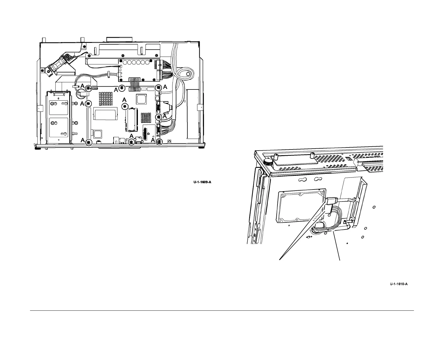
7. Remove the single board controller PWB, Figure 2.
Figure 2 Removal
Replacement
CAUTION
When installing the PWB cover, PL 3.11 Item 11, ensure that the PJ222 connector for the hard
disk drive/single board controller PWB harness is not unlatched.
1. Replacement is the reverse of the removal procedure.
NOTE: Before installing the harness guide plate, ensure that the harnesses are correctly
routed. Refer to REP 62.1.
2. Perform an Altboot, refer to GP 4 Machine Software.
REP 3.8 Hard Disk Drive
Parts List on PL 3.11
Removal
WARNING
Switch off the electricity to the machine. Refer to GP 14. Disconnect the power cord
from the customer supply while performing tasks that do not need electricity. Electricity
can cause death or injury. Moving parts can cause injury.
WARNING
Take care during this procedure. Sharp edges may be present that can cause injury.
1. Check via either the machine configuration sheet or Centreware Internet Services/Proper-
ties/General Setup/ Feature Installation if any optional features are enabled, e.g. McAfee
integrity control enablement. Obtain and note any necessary optional feature installation
keys, GP 48.
2. Pull out the image processing module.
3. Remove the Fax module if installed.
4. Remove the two harnesses from the hard disk drive, Figure 1.
Figure 1 Hard Disk Drive harness
1
Remove 9 screws marked A.
2
Remove the single board controller PWB.
1
Disconnect 2 harnesses.
2
Remove the tie wrap.
 Loading...


