February 2013
4-21
ColorQube® 9303 Family
REP 2.1
Repairs/Adjustments
REP 2.1 User Interface Assembly
Parts List on PL 2.10
Removal
WARNING
Switch off the electricity to the machine. Refer to GP 14. Disconnect the power cord
from the customer supply while performing tasks that do not need electricity. Electricity
can cause death or injury. Moving parts can cause injury.
Figure 1 ESD Symbol
CAUTION
Ensure that ESD procedures are observed during the removal and installation of the user inter-
face assembly.
NOTE: Detachment of the user interface (UI) control panel will enable the replacement of the
user interface control PWBA, PL 2.10 Item 2, user interface status PWBA, PL 2.10 Item 4 and
the user interface touch screen, PL 2.10 Item 3. Only remove the complete user interface
assembly when necessary, e.g reinstallation onto a new scanner assembly.
1. Open the front door. If the complete UI assembly is to be removed, remove the scanner
module, REP 62.1.
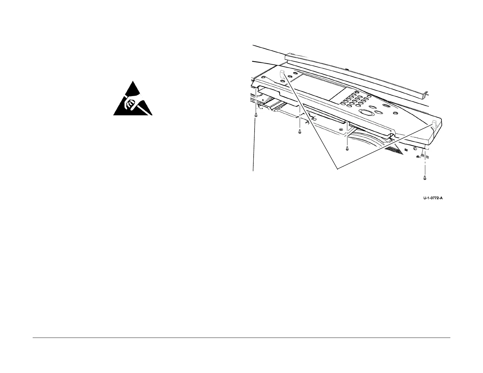
2. Prepare to detach the UI control panel, Figure 2.
Figure 2 Preparation
1
Remove 4 screws
NOTE: The UI control panel has 2
hooked retainers, located on the
underside at the left and right rear
corners.
 Loading...


