February 2013
6-259
ColorQube® 9303 Family
dC140
General Procedures/Information
dC140 Analog Monitor
Purpose
To provide tools to start (activate) and stop (deactivate) monitoring of specific analog compo-
nents. The nominal range of the analog value and, when monitoring is active, the current value
is displayed. The values are updated at least every second to allow the component state to be
monitored.
Refer to Table 1 for the component list.
Procedure
1. Enter service mode, GP 1.
2. Select the Diagnostics tab.
3. Select dC140 Analog Monitor. The dC140 Analog Monitor screen is displayed.
4. Scroll the table to display the available analog components.
5. Select the required item from the table.
6. A popup menu will be displayed, select start to confirm.
• The table will display a status against the selected component.
• While service mode is activated the components are not active so the value will not
change.
• To check the component either manipulate the component manually or make a note
of the value, exit Analog Monitor go to dC330 Component Control, to run the compo
-
nent and return to dC140 Analog Monitor.
• Multiple components may be selected.
• To stop monitoring select the required component and select stop.
• Selecting Close will stop monitoring all components.
7. Select Close to return to the Diagnostic Routine window.
8. Select Call Closeout to exit service mode.
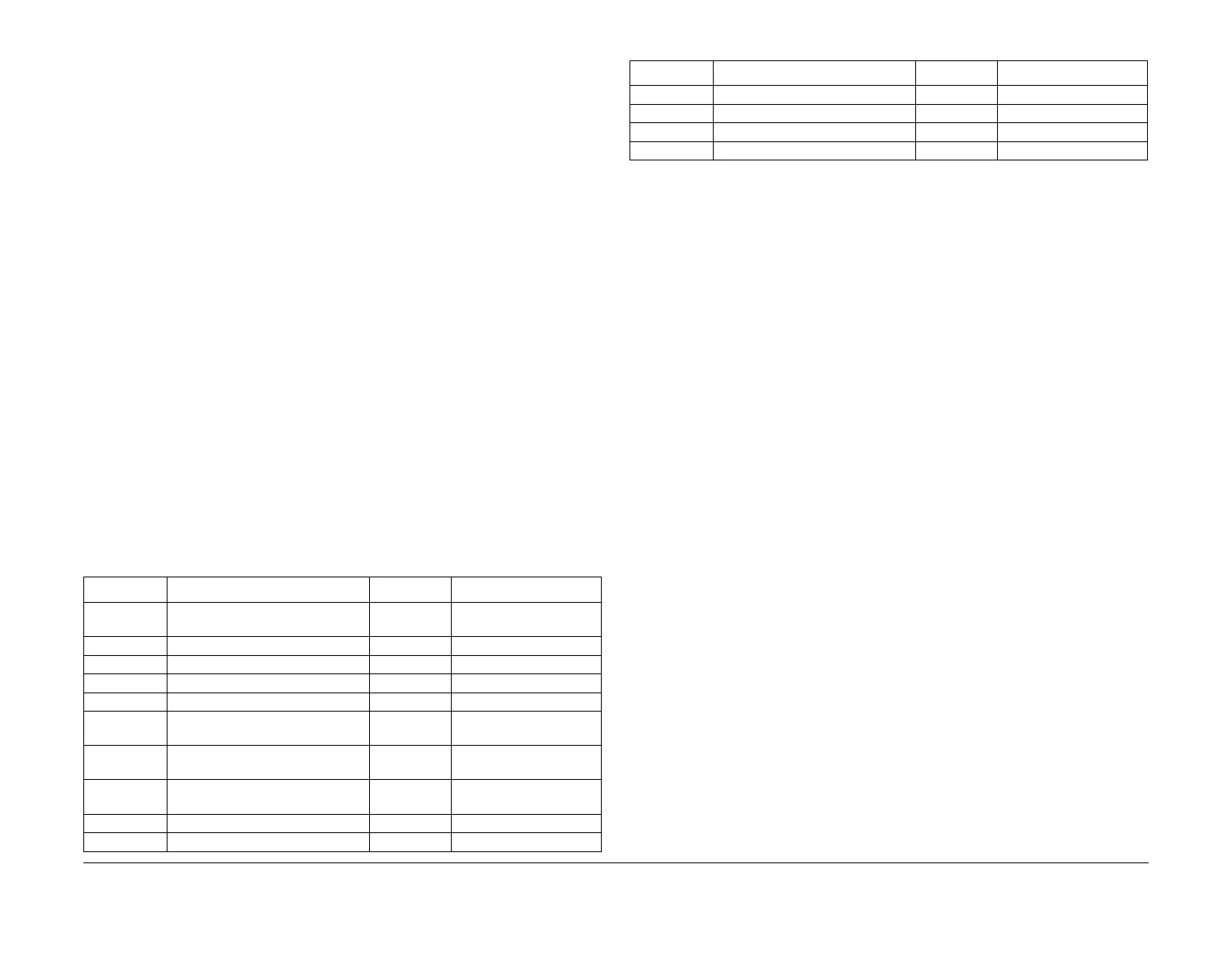
Table 1 Component List
ID Code Component Name Range Comments
010 - 010 Rear Transfix Flexure Encoder, PL
10.20 Item 5
0 - 65535 Display value in ticks
010 - 011 Rear Transfix Motor Encoder 0 - 65535 Display value in ticks
010 - 012 Front Transfix Flexure Encoder 0 - 65535 Display value in ticks
010 - 013 Front Transfix Motor Encoder 0 - 65535 Display value in ticks
042 - 100 Abatement Fan Tachometer 0 - 37500 Zero RPM with fan off
073 - 003 Tray 3 Elevator Encoder 0 - 255 Zero ticks with tray 3
down
074 - 415 Bypass Width Potentiometer 0 - 65535 Move guides to change
tick value
075 - 015 Tray 5 Elevator Encoder 0 - 255 Zero ticks with tray 5
down
082 - 100 Vert Trans Motor Encoder (M2) 0 - 65535 Display value in ticks
082 - 102 Horiz Trans Motor Encoder (M6) 0 - 65535 Display value in ticks
091 - 017 IOD Shuttle Motor Encoder 0 - 65535 Display value in ticks
094 - 101 Drum Drive Motor Encoder 0 - 65535 Display value in ticks
094 - 102 Drum Position Encoder 0 - 65535 Display value in ticks
094 - 103 Cleaning Unit Motor Encoder 0 - 65535 Display value in ticks
Table 1 Component List
ID Code Component Name Range Comments
 Loading...


