February 2013
6-46
ColorQube® 9303 Family
GP 14, GP 15
General Procedures/Information
Low Power Mode
Entry to low power mode is from Ready to Copy mode. In low power mode, the following condi-
tions apply:
• The Power button on the UI will flash.
• All 5V, 12V and 24V supplies are off.
• The single board controller hard disk is powered down.
• The UI backlight and display are powered down.
• The image marking engine thermal system is at low power settings. The printheads are
lowered onto the drum and the drum heated.
• The DADH and scanner are powered down.
• The AC supply to the LCSS or HVF is switched off.
• All power to the USB ports is switched off.
• The image marking engine fans are switched off
Sleep Mode
Entry to sleep mode is from low power mode. In sleep mode, the following conditions apply:
• The Power button on the UI is lit.
• All 5V, 12V and 24V supplies are off.
• The single board controller hard disk is powered down.
• The UI backlight and display are powered down.
• The image marking engine thermal system is at sleep settings. The printheads are
retracted. The drum heaters are powered down and the drum will not rotate.
• The DADH and scanner are powered down.
• Except for the door sensors, the 3 tray module is powered down.
• The AC supply to the LCSS or HVF is switched off.
• All power to the USB ports is switched off.
• The image marking engine fans are switched off
NOTE: Refer to GP 22 Electrical Power Requirements for further information.
GP 15 Location and Function of PWB LEDs
Purpose
Use this procedure to check the voltage and the communication status on the PWB.
Refer to
• Power Supply Unit
• Media Path Driver PWB
• Drum Driver PWB
• Marking Unit Driver PWB
• Printhead PWB
• IME Control PWB
• Single Board Controller PWB
• 3 Tray Module PWB
• LCSS PWB
• HVF PWB
• HVF Booklet Maker PWB
• Scanner PWB
Power Supply Unit
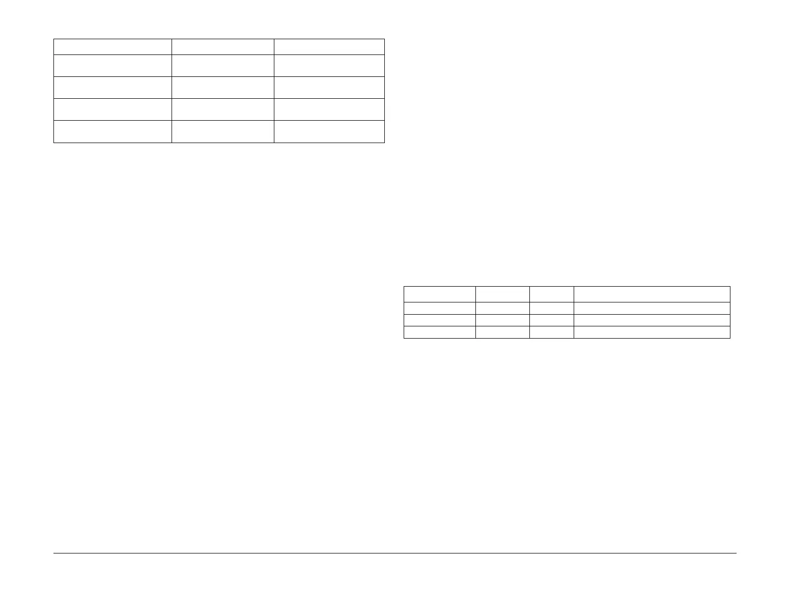
Table 1 indicates the states of the LED’s on a good working power supply unit, PL 1.15 Item 2.
Job activated with
Fast resume Off
5 minutes 60 minutes
Job activated with
Fast resume On
60 minutes 120 minutes
Scheduled mode (within sched-
uled times)
Not applicable (no low
power entry)
Not applicable (no low power
entry)
Scheduled mode (outside
scheduled times)
60 minutes 120 minutes
Table 1 Default settings
Mode Low Power Timeout Sleep Mode Timeout
Table 1 Power supply unit
LED ID LED colour Status Description
DS2 Green On +3.3V ESTAR present
DS7 Yellow On +5V present
DS1 Red On +50V present
 Loading...


