February 2013
4-187
ColorQube® 9303 Family
REP 12.49-171
Repairs/Adjustments
REP 12.49-171 Compiler Paddle Unit
Parts List on PL 12.115.
Removal
WARNING
Take care during this procedure. Sharp edges may be present that can cause injury.
WARNING
Switch off the electricity to the machine. Refer to GP 14. Disconnect the power cord
from the customer supply while performing tasks that do not need electricity. Electricity
can cause death or injury. Moving parts can cause injury.
1. Remove the front, rear and top covers REP 12.1-171.
2. Remove the HVF stapler assembly, REP 12.2-171.
3. Remove the compiler paddle motor assembly, REP 12.48-171.
NOTE: The motor coupler should detach with the motor assembly. If the coupler fails to
detach, remove the coupler from the paddle module assembly.
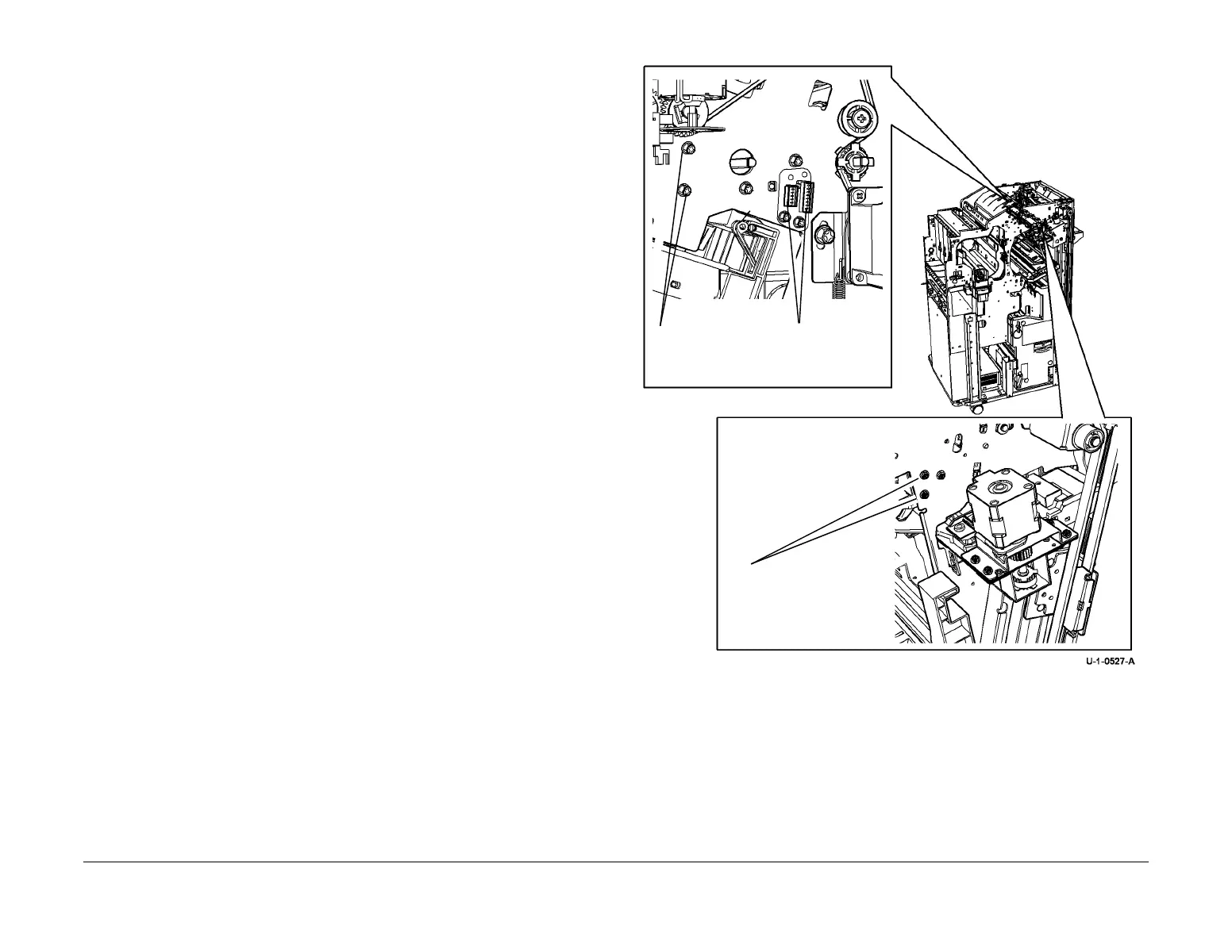
4. Remove the PJs and screws securing the ribbon cable connectors, Figure 1. Carefully
push the ribbon cable bulkhead connectors through the frame cut-outs.
Figure 1 Paddle Module Attachment
5. Remove the screws (front and rear) and the front grounding strap then manoeuvre the
module downwards, Remove the module through the stapler aperture, Figure 1.
Replacement
CAUTION
Do not damage or strain the paddle module ribbon cables or connectors
Reverse the removal procedures to replace the compiler paddle unit.
Use the correct screws to secure the compiler paddle unit; do not overtighten.
Paddle unit cable
connectors.
Paddle unit rear
screws.
Paddle unit
front screws.
 Loading...


