February 2013
6-73
ColorQube® 9303 Family
GP 21
General Procedures/Information
GP 21 Installation Space Requirements
Purpose
To outline the general space requirements to enable safe use and adequate access for service.
WARNING
Do not work in a confined space. 1 m (39 inches) space is needed for safe working.
WARNING
USA and Canada. Do not install this machine in a hallway or exit route that does not
have 1.12 m (44 inches) of space additional to the normal space requirements in front of
the machine. To conform with fire regulations this additional 1.12 m (44 inches) of space
is needed in front of the machine in hallway and exit routes.
Machine Height
• Machine height with the DADH lowered = 1155 mm (45.5 inches)
• Machine height with the DADH raised = 1467 mm (58 inches)
Machine Weight
• Basic machine with DADH weight = 218.5 kg (480.7 lbs.)
NOTE: Basic machine weight does not include the weight of a finisher or tray 5.
Optional Tray
• Tray 5 = 30 kg (66 lbs.)
Finishers
• OCT = 2 kg (4.5 lbs.)
• 2K LCSS = 30 kg (66.5 lbs.)
• HVF = 72.8 kg (160 lbs.)
• HVF BM with PPI and Tri-folder = 100.3 kg (220.7 lbs.)
Machine dimensions and Installation Space Requirements
ColorQube Standalone Digital Copier
Table 1 shows the dimensions of the ColorQube 9301/9302/9303 standalone digital copier (no
media shelf) machines and the installation space required for safe operation.
NOTE: The dimensions shown in Table 1 allow for a 1 metre (39.4 inches) minimum safety
workspace around the machine. To acquire the minimum safety workspace it may be neces
-
sary to move the machine within the area specified.
A gap of 100 mm is required at the rear of the IOT for airflow to the fans. This is also sufficient
for the DADH when raised.
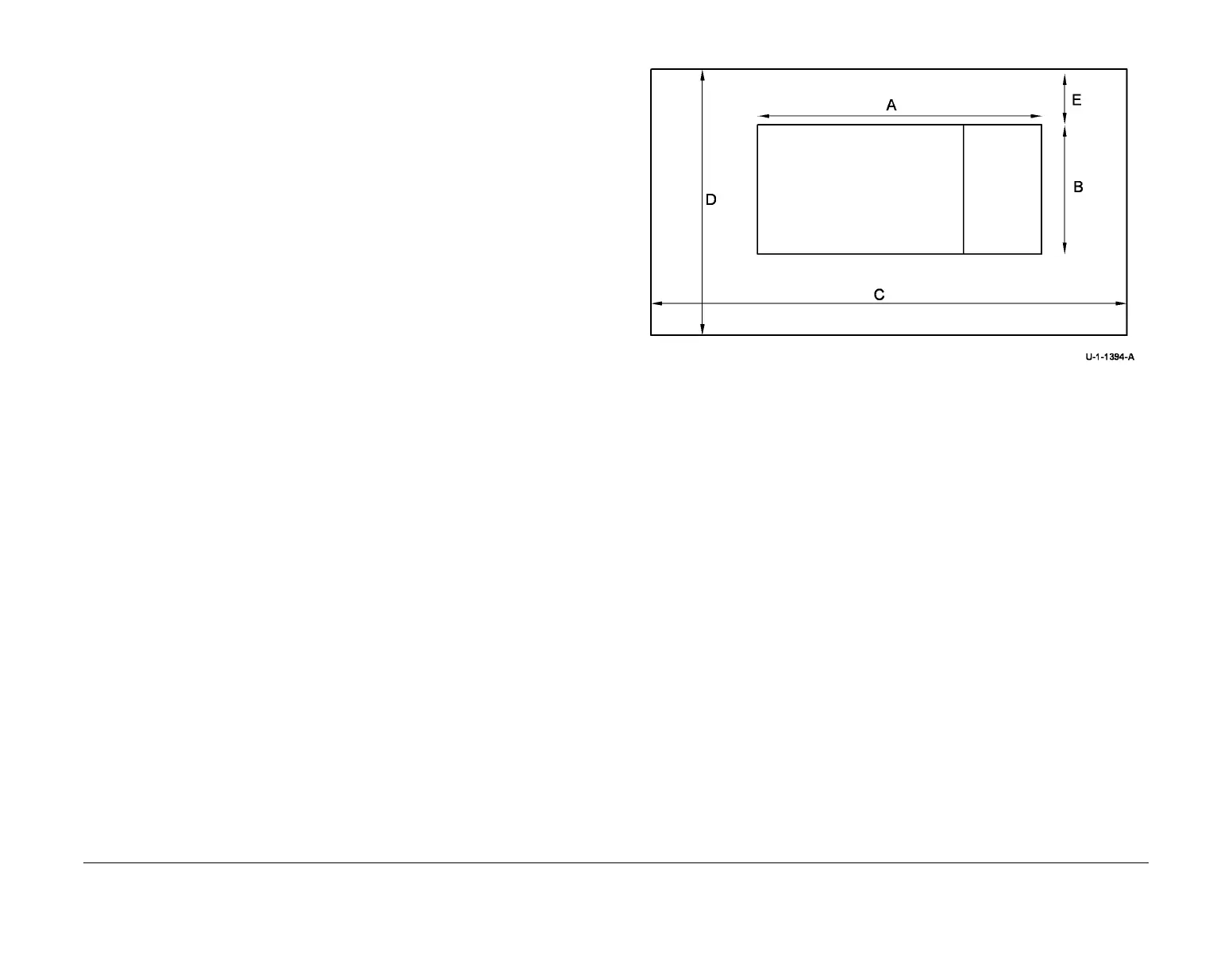
Figure 1 represents a plan view of a machine installation and is to be read in conjunction with
Table 1. The dimensions A and B outline a footprint of the machine within the boundary of safe
operation, dimensions C and D. The dimension E indicates the area required for airflow / work
-
space at the rear of the machine.
Figure 1 Installation plan
Front
 Loading...


