February 2013
4-25
ColorQube® 9303 Family
REP 3.1
Repairs/Adjustments
REP 3.1 IME Controller PWB
Parts List on PL 92.10
Removal
WARNING
Switch off the electricity to the machine. Refer to GP 14. Disconnect the power cord
from the customer supply while performing tasks that do not need electricity. Electricity
can cause death or injury. Moving parts can cause injury.
Figure 1 ESD Symbol
CAUTION
Ensure that ESD procedures are observed during the removal and installation of the IME con-
troller PWB.
1. Open the front door
2. Remove the inner cover, PL 81.11 Item 2.
3. Pull out the marking unit, GP 6.
4. Remove the marking unit enclosure cover, PL 91.10 Item 18.
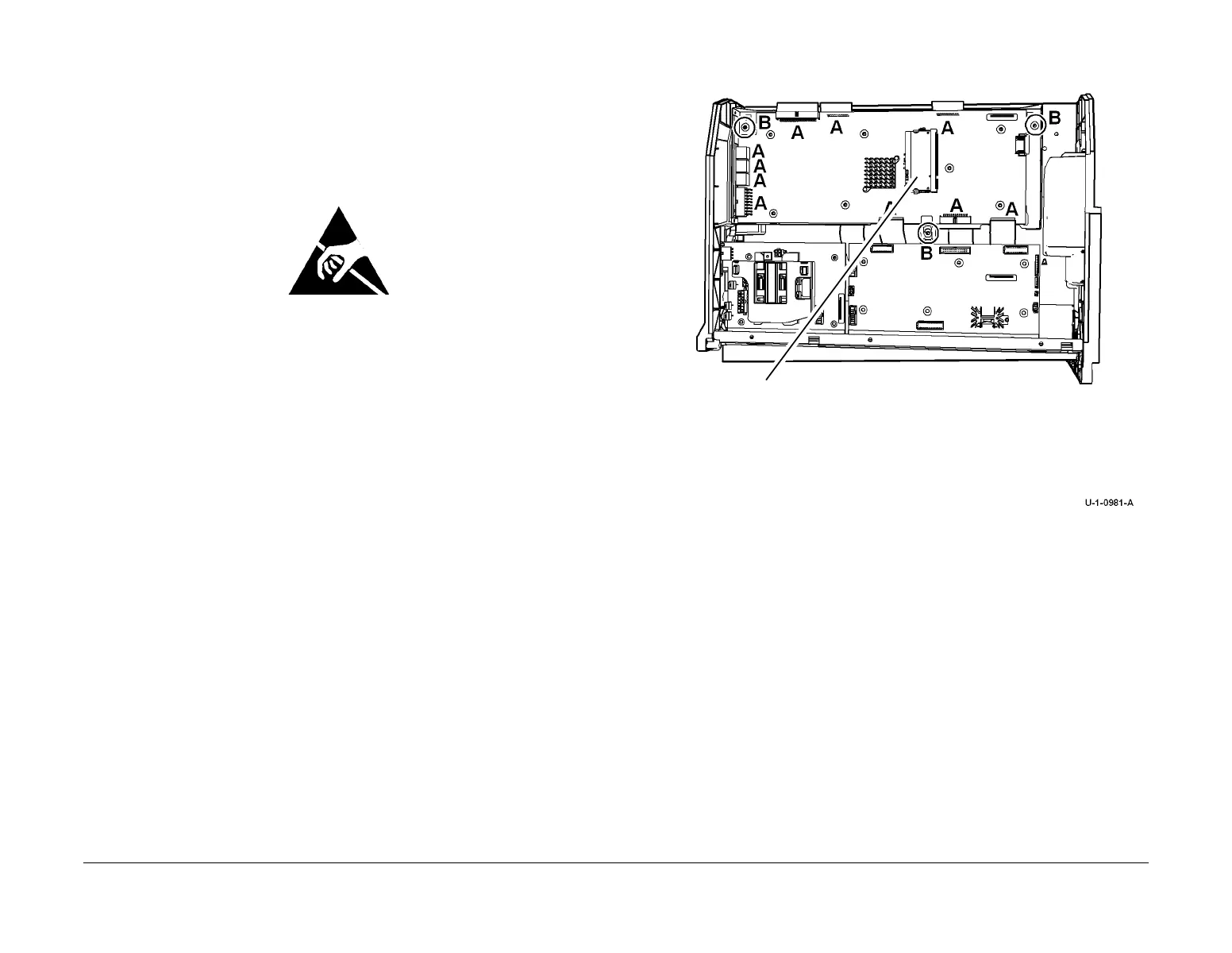
5. Remove the IME controller PWB, Figure 2.
Figure 2 IME controller PWB removal
Replacement
1. Replacement is the reversal of the removal process.
2. Transfer the NVRAM from the failed PWB and install onto the new PWB, Figure 2.
3. Install the new NVRAM onto the failed IME Controller PWB to be returned.
If both IME controller PWB and IME NVRAM chip are replaced at the same time. Then
perform the following:
a. dC977 Drum Runout Calibration.
b. dC625 Registration / Preheat Calibration.
c. The front and rear transfix calibration values need to be entered into dC978. The val-
ues are located on the front of the drum frame.
d. Empty the waste tray, since the NVM tracking purge mass has been lost.
e. Enter dC131 NVM Read / Write at location 492-70 Prints On This Drum and enter
the page count of the machine.
1
Disconnect PJs marked A.
2
Remove screws marked B then remove the PWB.
3
Transfer the NVRAM
 Loading...


