February 2013
4-31
ColorQube® 9303 Family
REP 3.6, REP 3.7
Repairs/Adjustments
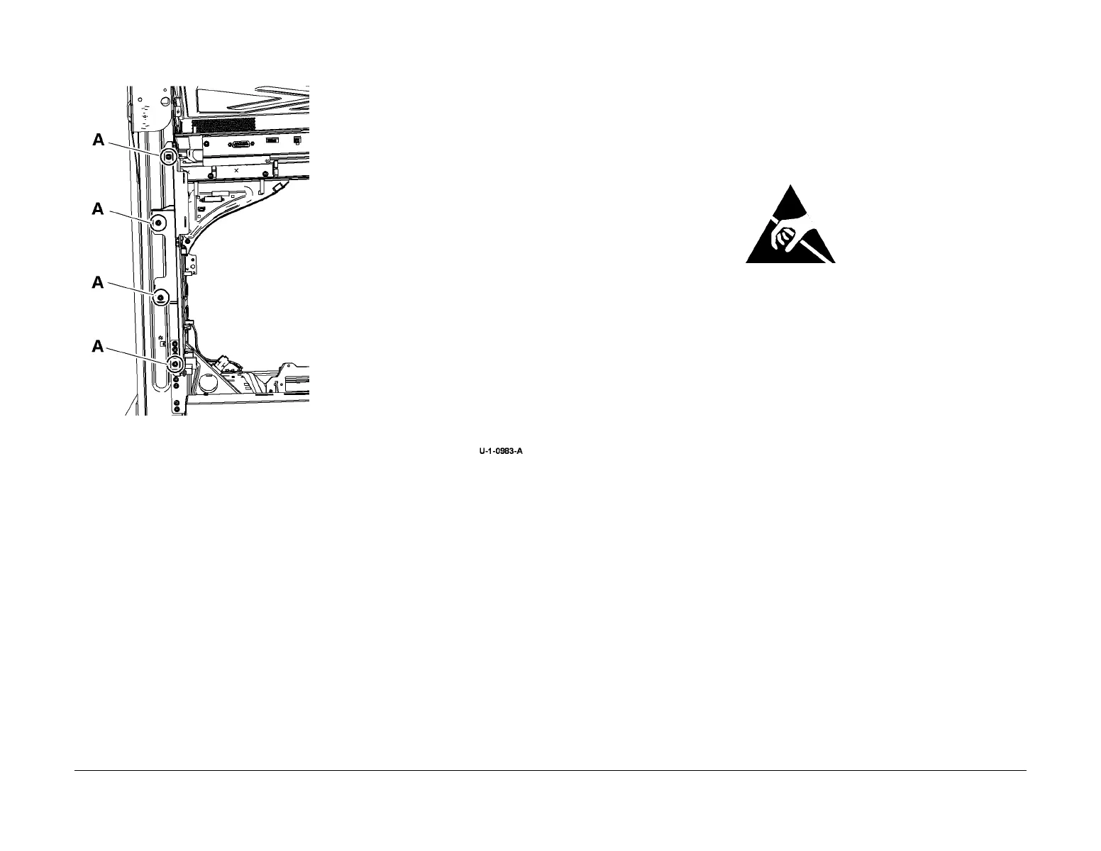
4. Remove the drum driver PWB, Figure 3.
Figure 3 Drum driver PWB removal
Replacement
Replacement is the reverse of the removal procedure.
REP 3.7 Single Board Controller PWB
Parts List on PL 3.11
Removal
WARNING
Switch off the electricity to the machine. Refer to GP 14. Disconnect the power cord
from the customer supply while performing tasks that do not need electricity. Electricity
can cause death or injury. Moving parts can cause injury.
Figure 1 ESD Symbol
CAUTION
Ensure that ESD procedures are observed during the removal and installation of the single
board controller PWB.
1. If installed, remove the following components:
• Foreign device interface PWB, PL 3.11 Item 14.
2. If a new single board controller PWB is to be installed, remove the following components:
• System memory, PL 3.11 Item 4.
• NVM module PWB, PL 3.11 Item 17.
• EPC memory PWB, PL 3.11 Item 21.
• Product enablement key (SIM), PL 3.11 Item 22.
3. Disconnect all connectors on the rear of the image processing module. Pull out the image
processing module.
4. Remove the harness guide plate, PL 3.11 Item 24.
5. Remove the PWB cover, PL 3.11 Item 11.
6. Disconnect all connectors on the single board controller PWB.
CAUTION
Lift the single board controller PWB. Do not slide the PWB in the image processing module.
The PWB have components on the underside that can be easily damaged.
1
Remove screws marked A
then remove the PWB.
 Loading...


