February 2013
4-157
ColorQube® 9303 Family
REP 12.26-171, REP 12.27-171
Repairs/Adjustments
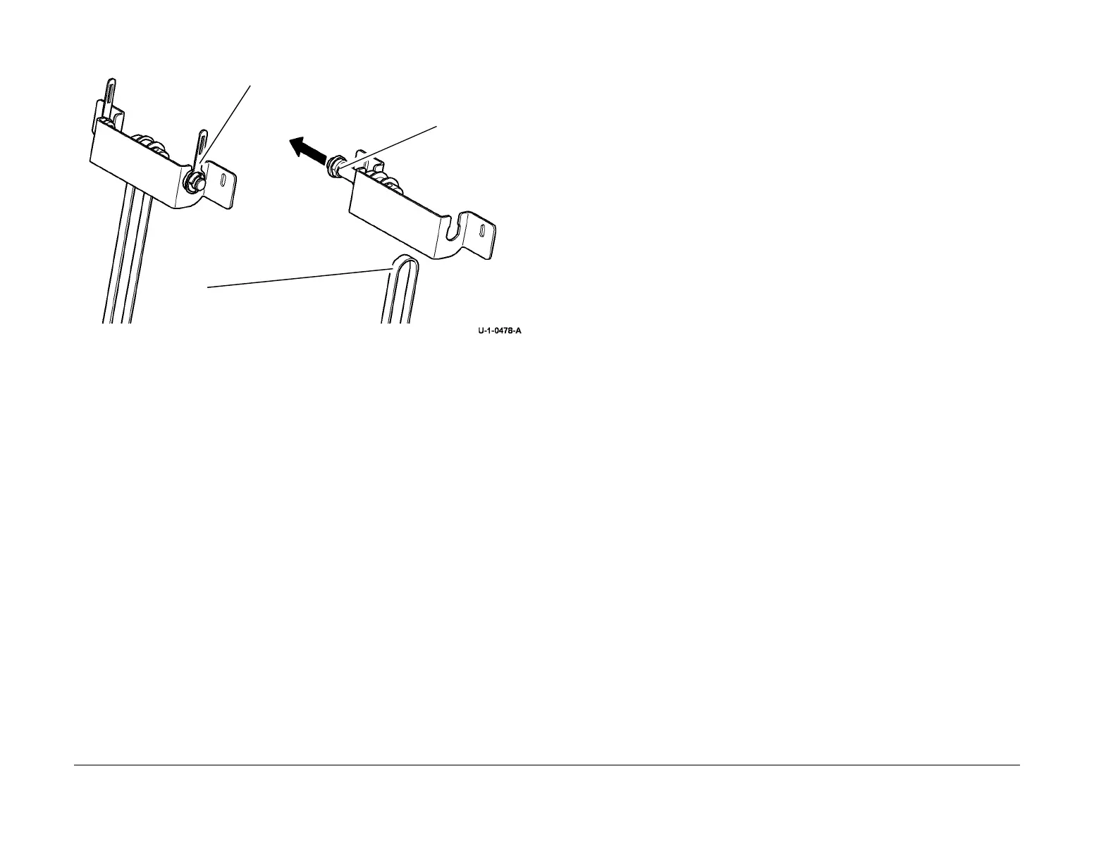
13. Figure 4, remove the BM backstop belt.
Figure 4 Backstop belt removal
Replacement
Reverse the removal procedure to replace the removed components. Allow the BM backstop
belt to be tensioned correctly before the bracket assembly securing screws are tightened.
Refer to Figure 3.
REP 12.27-171 BM Staple Heads
Parts List on PL 12.185.
Removal
WARNING
Take care during this procedure. Sharp edges may be present that can cause injury.
WARNING
Switch off the electricity to the machine GP 14. Disconnect the power cord from the cus-
tomer supply while performing tasks that do not need electricity. Electricity can cause
death or injury. Moving parts can cause injury.
1. Fully pull out the BM module.
2. Remove the relevant staple head cover, PL 12.185 Item 14.
3. Pull the stapler bracket handle, PL 12.185 Item 9. Open the staplers fully.
NOTE: If a 5.5 mm socket and short extension is not available or access to the staple head
securing screws is difficult, remove the BM stapler bracket assembly, REP 12.28-171, then
remove the relevant staple head.
4. Figure 1, remove the relevant staple head.
1
Remove KL-clip, tensioner
link and bearing.
2
Slide the shaft
to one side.
3
Remove the belt.
 Loading...


