February 2013
4-165
ColorQube® 9303 Family
REP 12.30-171
Repairs/Adjustments
REP 12.30-171 BM Tamper Assembly and Tamper 1 Motor
Parts List on PL 12.155.
Purpose
This procedure is used to repair the following components:
• BM tamper 1 motor, PL 12.155 Item 3.
• BM rear tamper arm, PL 12.155 Item 5.
• BM front tamper arm, PL 12.155 Item 6.
• BM rear tamper rack, PL 12.155 Item 7.
• BM front tamper rack, PL 12.155 Item 8.
• BM rear tamper assembly, PL 12.155 Item 9.
• BM front tamper assembly, PL 12.155 Item 10.
• BM tamper gear,PL 12.155 Item 11.
• BM tamper bracket, PL 12.155 Item 12.
• BM tamper rack guide, PL 12.155 Item 13.
• BM tamper guide plate, PL 12.155 Item 15.
• BM rear tamper finger, PL 12.155 Item 16.
• BM front tamper finger, PL 12.155 Item 17.
Removal
WARNING
Switch off the electricity to the machine GP 14. Disconnect the power cord from the cus-
tomer supply while performing tasks that do not need electricity. Electricity can cause
death or injury. Moving parts can cause injury.
WARNING
Take care during this procedure. Sharp edges may be present that can cause injury.
1. Open the HVF BM front door and fully pull out the BM module.
2. Remove the crease blade knob (6d), PL 12.150 Item 4.
3. Remove the crease roll handle (6c), PL 12.150 Item 5.
4. Remove the BM front cover, PL 12.150 Item 3.
5. Remove the left frame plate, PL 12.160 Item 17.
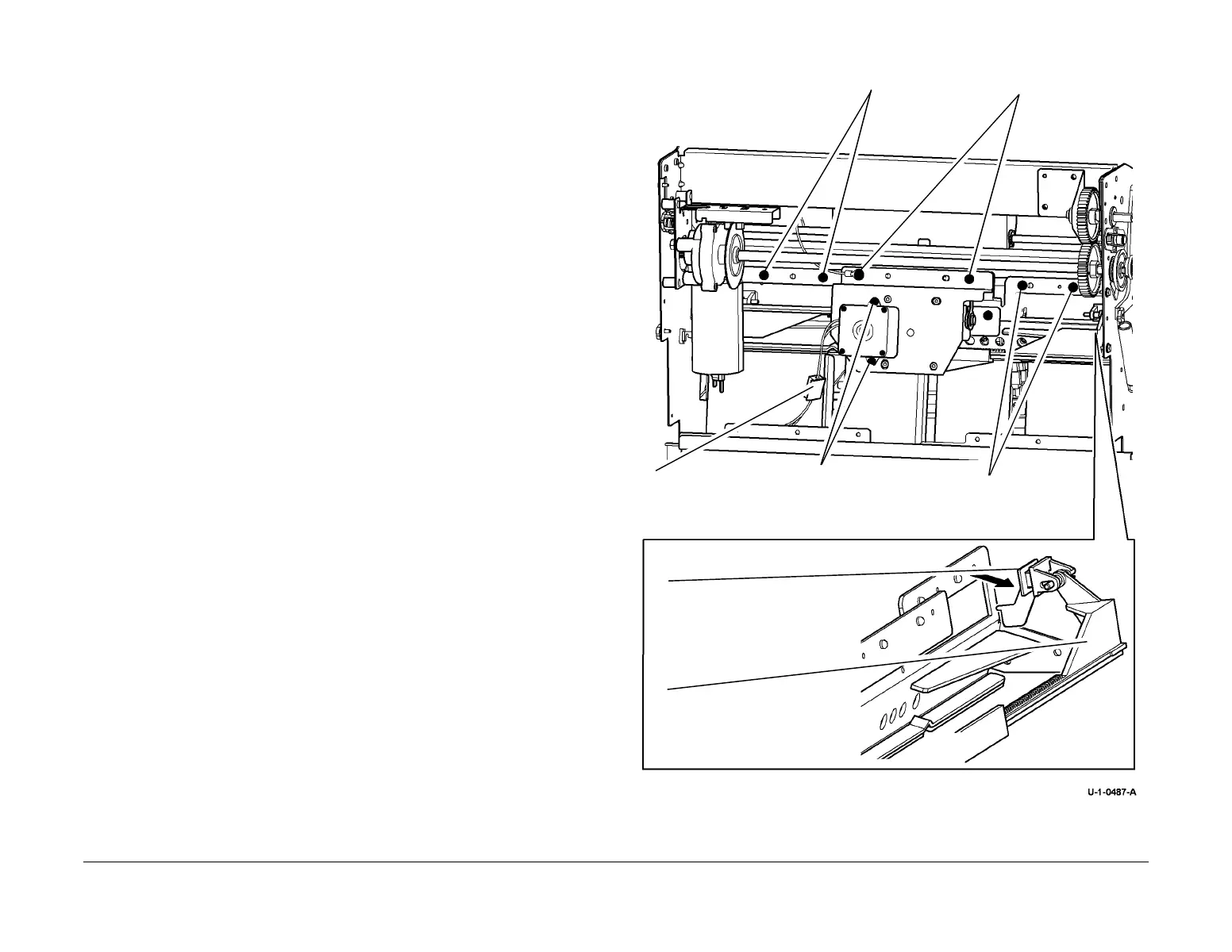
6. Figure 1, remove the tamper assembly.
Figure 1 Tamper assembly removal
Remove 2 screws
1
Remove the cover and
disconnect the harness.
Remove 2 screws
and earth connecto
6
Move the tampers to align with the
slots to release each tamper from the
slot.
7
Remove the tamper
assembly.
2
Remove 2 screws then
remove the motor.
3
Remove 2 screws.
 Loading...


