February 2013
4-422
ColorQube® 9303 Family
ADJ 75.2, ADJ 75.3
Repairs/Adjustments
ADJ 75.2 Tray 5 Module to Machine Alignment
Parts List on PL 75.62
Purpose
To correctly align the tray 5 module to achieve correct top edge registration and reliable trans-
fer of paper from the tray 5 module to the machine.
Adjustment
WARNING
Ensure that the electricity to the machine is switched off while performing tasks that do
not need electricity. Refer to GP 14. Disconnect the power cord. Electricity can cause
death or injury. Moving parts can cause injury.
The adjustment must be performed in the following order:
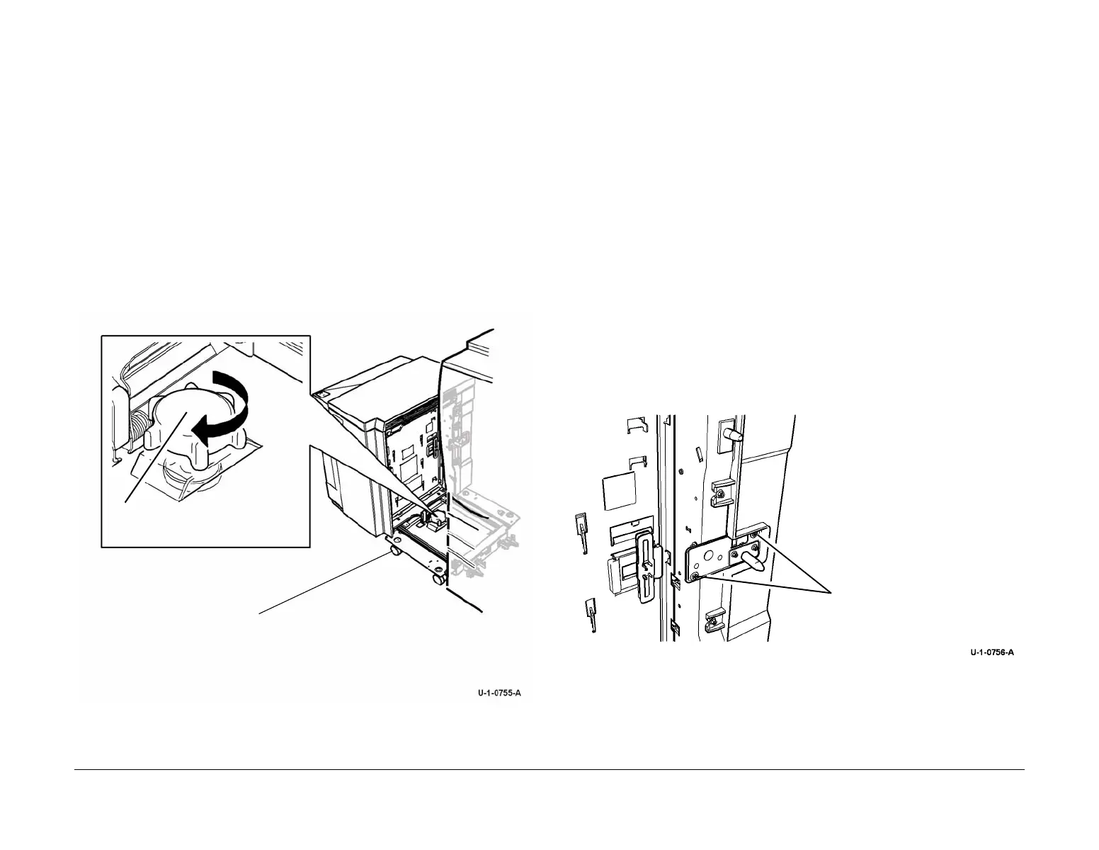
1. Figure 1, turn the hand wheel in the centre of the tray 5 module to raise the casters off of
the floor.
2. Check the registration, refer to dC625 Registration / Preheat Calibration.
Figure 1 Machine to tray 5 alignment
ADJ 75.3 Tray 5 Module Tray Alignment
Parts List on PL 75.64
Purpose
To align the tray 5 module paper tray with the paper trays in the IOT module. Use this adjust-
ment when the top edge registration cannot be achieved using dC625 Registration / Preheat
Calibration.
NOTE: Perform ADJ 75.2, Tray 5 Module to Machine Alignment, before starting this adjust-
ment procedure. Use both ADJ 75.2 and this adjustment to achieve correct hole punch align-
ment.
Before performing this adjustment return the NVM values for tray 5 to the nominal values.
Adjustment
WARNING
Ensure that the electricity to the machine is switched off while performing tasks that do
not need electricity. Refer to GP 14. Disconnect the power cord. Electricity can cause
death or injury. Moving parts can cause injury.
Make a sample print and determine which way and how far the tray needs to be moved. After
the adjustment is made, take a sample print.
1. Loosen the two screws on the docking pin bracket, Figure 1.
Figure 1 Docking pin bracket
2. Turn the adjusting screw to move the docking pin bracket to the front or to the rear, Figure 2
1
Turn the hand wheel to
obtain alignment
2
Raise front and rear casters off of the
floor
1
Loosen two screws
 Loading...


