February 2013
4-60
ColorQube® 9303 Family
REP 10.1, REP 10.2
Repairs/Adjustments
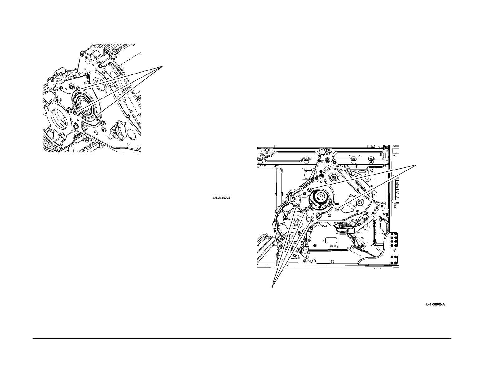
6. Remove transfix roller, Figure 2.
Figure 2 Transfix roll removal
Replacement
1. Replacement is the reverse of the removal procedure.
2. Clean the transfix roller and housing with a dry cloth. Remove all grease that is not neces-
sary.
NOTE: High pressure bearing grease, PL 26.11 Item 3, is used on the outside diameter of
the transfix roller bearing holder. During normal removal and replacement the existing
bearing grease used during manufacture will be sufficient. Only apply grease when both
sides of any bearing surface are being replaced, or if the surfaces have been wiped clean.
Apply the grease very sparingly.
3. Ensure that the ground lead between the top transfix roller screw and the front drum
frame is reconnected.
REP 10.2 Front Transfix Linkage and Gear Kit
Parts List on PL 10.20
Removal
WARNING
Switch off the electricity to the machine. Refer to GP 14. Disconnect the power cord
from the customer supply while performing tasks that do not need electricity. Electricity
can cause death or injury. Moving parts can cause injury.
WARNING
Take care during this procedure. Sharp edges may be present that can cause injury.
CAUTION
Use care when working near the drum. The drum can be damaged easily, which will cause
print quality defects.
1. Remove the transfix roller, REP 10.1.
2. Remove the front drum shroud, PL 94.20 Item 7.
3. Prepare to remove the front plate, Figure 1.
Figure 1 Preparation
2
Install the 3 screws into the
adjacent threaded holes.
Gradually tighten each screw
in sequence to remove the
bearing evenly.
3
Remove the transfix roller
from the front
1
Take note of the cautions
above.
1
Remove 3 T30 screws.
2
Remove 2
long screws
and washers
 Loading...


